

Craft Drill Controller
for semi-automated PCB drilling — and more
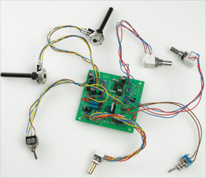
Designing and making a printed circuit board (PCB) for a project has many advantages over using strip board, but there is one big disadvantage – drilling the holes. Our Craft Drill Controller takes away some of the tedium of this task by semi-automating the way a 12V mini drill has its speed controlled, so saving time and drill bits!
This is a MEMBER ONLY article. You need a subscription to read this article.
- Unlimited access to online Member Only articles
- 3 new editions Elektor Magazine (digital)
- More than 5000 Gerber files
- 20% member discount on e-books (at elektor.com)
- 10% member discount on Products (at elektor.com)
Available from €5.33 per month.
What is Members Only
Elektor is committed to providing high-quality content on electronics, catering to tens of thousands of paying members. As part of this commitment, Elektor has launched Premium, an initiative that offers exclusive online articles to members sometimes even before they appear in the magazine.
Every day, members can access in-depth articles that showcase the best of Elektor's premium content.
This initiative aims to reward members with early access. Once logged in, members can easily enjoy this exclusive content and engage in discussions about featured projects. While Premium adds to the existing resources available, Elektor will continue to provide a wealth of free information.
Join the Elektor community today to take advantage of Premium and other benefits!
Materials
Component list
Resistors
R1,R28,R29 = 100
R2,R6,R9,R10,R15,R18,R21,R24 = 1k
R3 = 15Ω 2W
R4,R30 = 2kΩ2
R5,R12,R13 = 15k
R7,R8,R11,R16,R17,R22,R23 = 4kΩ7
R14,R19 = 2kΩ7
R20, R25 = 10k
R26,R27 = 100k
P1,P2 = 5kΩ linear-law potentiometer
P3,P4 = 10kΩ linear-law potentiometer
P5 = 50kΩ linear-law stereo potentiometer
Capacitors
C1 = 100nF
C2 = 470nF
C3,C4,C7,C8 = 220μF 25V radial electrolytic
C5,C6 = 220nF
C9,C10 = 22nF
Semiconductors
D1,D6,D7,D8,D9,D10,D11 = 1N4148
D2,D3,D4,D5,D12,D13 = LED, low current
T1,T4 = BS170
T2,T3,T8,T9,T10,T11= BC560C
T5,T6,T14,T15,T16,T17= BC550C
T7 = TIP122
T12,T13 = BS250P (watch suffix P)
IC1 = L7805CV
Miscellaneous
S1 = on/off switch, 1 make contact
S2 = on/off switch, 1 make contact
S3 = footswitch, on/off, 1 make contact, see text.
S4 = single-pole changeover switch
S5 = single-pole changeover switch
PCB, ref. 060291-I from ThePCBShop; free artwork download # 060291-1.zip
Front & rear panel artwork files
Discussion (0 comments)