Article
Anti-Standby Switch
Also works with a remote control!
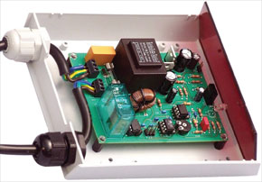
Energy Saving may well be a must-have feature for home entertainment products sold today but there are still millions of older and even not-so-old appliances that are guzzling far too much juice in the all too convenient standby mode. The anti-standby switch described here saves the planet’s energy—and yours too!
Materials
Gerber file
CAM/CAD data for the PCB referred to in this article is available as a Gerber file. Elektor GREEN and GOLD members can exclusively download these files for free as part of their membership. Gerber files allow a PCB to be produced on an appropriate device available locally, or through an online PCB manufacturing service.
Elektor recommends the Elektor PCB Service service from its business partner Eurocircuits or AISLER as the best services for its own prototypes and volume production.
The use of our Gerber files is provided under a modified Creative Commons license. Creative Commons offers authors, scientists, educators and other creatives the freedom to handle their copyright in a more free way without losing their ownership.
PCB
Component list
Resistors
R1,R3 = 820Ω
R2 = 3kΩ3
R4 = 2kΩ4, 1%
R5,R6,R7,R10 = 10kΩ
R8 = 2kΩ2
R9 = 220kΩ
R11 = 470kΩ
R12 = 1kΩ8
R13 = 100Ω
R14 = 220Ω
R15 = 22kΩ
P1 = 47kΩ
Capacitors
C1 = 100nF (250VAC)
C2,C4 = 470µF (16V)
C3,C11 = 10µF (16V)
C5 = 100µF (16V)
C6,C7,C9,C10 = 100nF (63V)
C8 = 220nF (63V)
C12 = 10nF (63V)
Semiconductors
D1,D2 = BAT43 (Schottky)
LED1 = LED, 5 mm, red
Br1 = B40C800, round case, 40V piv, 0.8A)
IC1 = LM317T (T0220 case)
IC2 = LM337T (T0220 case)
IC3 = MC34151
IC4 = ATtiny25-10V*, programmed, order code 070797-41 from Elektor Shop
IC5 = TSOP 1736 (36 kHz IR-receiver*)
IC6 = TLC272 or TL062*
Miscellaneous
F1 = fuse 3.15AT (slow) with PCB mount holder and cap
Re1 = 12V bistable* (1 x co) with 16-A contact, e.g. Finder # 40.61.6 12V (www.reichelt.de)
S1 = pushbutton, 1 make contact
Tr1 = mains transformer, 2×7.5V* @ 1.5 VA
Tr2 = 2A ring-core suppressor coil (with 4 turns 0.5 mm2)*
K1,K2 = 3-way PCN terminal block
K3 = 6-way DIL pinheader (2×3 pins)
PCB, order code 070797-1 from the Elektor Shop
Discussion (0 comments)