

Surround Light
The analogue approach
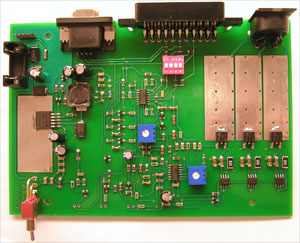
The operating principle consists of measuring the average colour of an image and using colour LEDs to emit the same colour in order to ‘paint’ an im
This is a MEMBER ONLY article. You need a subscription to read this article.
- Unlimited access to online Member Only articles
- 3 new editions Elektor Magazine (digital)
- More than 5000 Gerber files
- 20% member discount on e-books (at elektor.com)
- 10% member discount on Products (at elektor.com)
Available from €5.33 per month.
What is Members Only
Elektor is committed to providing high-quality content on electronics, catering to tens of thousands of paying members. As part of this commitment, Elektor has launched Premium, an initiative that offers exclusive online articles to members sometimes even before they appear in the magazine.
Every day, members can access in-depth articles that showcase the best of Elektor's premium content.
This initiative aims to reward members with early access. Once logged in, members can easily enjoy this exclusive content and engage in discussions about featured projects. While Premium adds to the existing resources available, Elektor will continue to provide a wealth of free information.
Join the Elektor community today to take advantage of Premium and other benefits!
Materials
Gerber file
CAM/CAD data for the PCB referred to in this article is available as a Gerber file. Elektor GREEN and GOLD members can exclusively download these files for free as part of their membership. Gerber files allow a PCB to be produced on an appropriate device available locally, or through an online PCB manufacturing service.
Elektor recommends the Elektor PCB Service service from its business partner Eurocircuits or AISLER as the best services for its own prototypes and volume production.
The use of our Gerber files is provided under a modified Creative Commons license. Creative Commons offers authors, scientists, educators and other creatives the freedom to handle their copyright in a more free way without losing their ownership.
Component list
R1-R6,R14,R15,R20,R39,R52,R61,R62,R65,R66,R67 = 10kΩ (SMD 1206)
R7,R8,R9,R13,R17,R18,R19,R31,R49,R50,R51,R57 = 3kΩ9 (SMD 1206)
R10,R11,R12 = 68kΩ (SMD 1206)
R16,R53,R56 = 1kΩ (SMD 1206)
R21,R32,R43,R45,R47,R54,R60 = 4kΩ7 (SMD 1206)
R22,R23,R24,R36,R40,R41,R42,R58 = 1kΩ (SMD 1206)
R25,R27,R29 = 6Ω8 (SMD 2512)
R26,R28,R30,R33,R44,R46 = 1Ω8 (0207)
R34 = 220kΩ(SMD 1206)
R35 = 1MΩ (SMD 1206)
R37,R59 = 680Ω (SMD 1206)
R38 = 47kΩ (SMD 1206)
R63 = 2kΩ2 (SMD 1206)
R64 = 6kΩ8 (SMD 1206)
R68 = 1Ω (SMD 1206)
R48,R55,R69 = 75Ω (SMD 1206)
P1 = 10kΩ
P2 = 1kΩ
Capacitors
C1-C4,C7-C12,C14,C15 = 100nF (SMD 1206)
C22 = 10nF (SMD 1206)
C21,C23 = 1nF (SMD 1206)
C16 = 470pF (SMD 1206)
C5,C13,C17-C20 = 100μF 25V
C6 = 10μF 25 V
Inductors
L1 = 47μH (Würth 12x12)
L2-L5 = choke, 91 Ω @ 100 MHz (SMD 1808)
Semiconductors
D1-D8,D11-D14,D21,D22 = LL4148 (SMD SOD-80)
D9,D10,D16,D20 = BZX84C5V6 (SMD SOT-23)
D17,D18,D19 = LED, 3mm, red
D23= RS3K (SMD SMC)
D15,D24 = 30BQ040 (SMD SMC)
T1,T2,T3 = MJD44H11 (SMD DPAK-N)
T4,T5,T6 = FDS6630 (SMD SO-8)
T7-T12,T14 = BC817 SMD SOT-23)
T13 = BC807 (SMD SOT-23)
IC1,IC2 = LM324 (SMD SO14)
IC3 = LM2592 (SMD SOT-263)
D25 = Luxeon LED, red (LXK2-PD12-R00)
D26 = Luxeon LED, green (LXK2-PM14-U00)
D27 = Luxeon LED, blue (LXK2-PB14-N00)
Miscellaneous
S1 = single-pole on/off switch (Farnell # 9575502)
S2 = 4-way DIP switch
K1 = 4-way SIL pinheader
K2,K3 = 5-way DIN socket
K4 = DC supply socket, PCB mount
K5 = VGA socket, PCB mount
K6 = SCART socket, PCB mount
F1 = fuse, 1A slow, with PCB mount holder
Enclosure, e.g. Vero # 16-3638089
PCBs # 070491-1 and 070491-2, see Elektor Shop section or www.elektor.com
Discussion (0 comments)