

TV Surround Light
The digital approach
This is a MEMBER ONLY article. You need a subscription to read this article.
- Unlimited access to online Member Only articles
- 3 new editions Elektor Magazine (digital)
- More than 5000 Gerber files
- 20% member discount on e-books (at elektor.com)
- 10% member discount on Products (at elektor.com)
Available from €5.33 per month.
What is Members Only
Elektor is committed to providing high-quality content on electronics, catering to tens of thousands of paying members. As part of this commitment, Elektor has launched Premium, an initiative that offers exclusive online articles to members sometimes even before they appear in the magazine.
Every day, members can access in-depth articles that showcase the best of Elektor's premium content.
This initiative aims to reward members with early access. Once logged in, members can easily enjoy this exclusive content and engage in discussions about featured projects. While Premium adds to the existing resources available, Elektor will continue to provide a wealth of free information.
Join the Elektor community today to take advantage of Premium and other benefits!
Materials
Gerber file
CAM/CAD data for the PCB referred to in this article is available as a Gerber file. Elektor GREEN and GOLD members can exclusively download these files for free as part of their membership. Gerber files allow a PCB to be produced on an appropriate device available locally, or through an online PCB manufacturing service.
Elektor recommends the Elektor PCB Service service from its business partner Eurocircuits or AISLER as the best services for its own prototypes and volume production.
The use of our Gerber files is provided under a modified Creative Commons license. Creative Commons offers authors, scientists, educators and other creatives the freedom to handle their copyright in a more free way without losing their ownership.
Extra info / Update
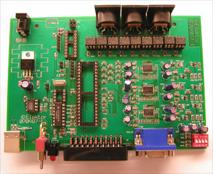
In the parts list in the printed magazine, the designations IC3 and IC4 should be interchanged. This does not affect the PCB or the circuit diagram.
All passive SMD parts are rectangular shape, footprint SMD1206.
Of the ADC1175JM and ADC1175TC mentioned in the article, only the –JM version is a discontinued part. The PCB has been designed to accept both versions.
LED light bars are available from, among others, www.reichelt.de (e.g. # LED 13,5RGB 3W).
Contrary to what is stated in the article text on page 28, ready-built boards are not available through the Elektor Shop.
Update: 15 May 2008
New firmware uploaded. Added bootloader.
Component list
R1,R5-R20,R22-R29,R40,R42-R47,R54,R59,R63,R68,R72,R77 = 100Ω
R2,R3 = 22Ω
R4,R21,R30,R39, = 4kΩ7
R31-R38,R41 = 180Ω
R48 = 680Ω
R49,R52,R61,R70 = 75Ω
R50 = 620Ω
R51 = 680kΩ
R53,R62,R71 = 3kΩ6
R55,R64,R73 = 120Ω
R56,R65,R74 = 10kΩ
R57,R66,R75 = 8kΩ2
R58,R67,R76 = 220Ω
R60,R69,R78 = 47Ω
Capacitors
C3 = 470nF
C4,C5,C7,C8,C10-C14,C21,C22,C23,C30,C31,C32 = 100nF
C9 = 560pF
C1,C20,C29 = 100pF
C2,C15-C19,C24-C28,C33-C36 = 10μF 25V
C6 = 220μF 25V
Semiconductors
D1-D4 = LL4148
D5 = LL4007 (SOD-106)
D6 = LED, 5mm, red
T3,T6,T9 = BC857
T1,T2,T4,T5,T7,T8 = BC847
IC1 = PIC18F4550-I/P, programmed, Elektor Shop # 070487-41
IC2 = PIC16F628-20I/P, programmed, Elektor Shop # 070487-42
IC4 = ICS502 (SO8)
IC3 = 7805T
IC5 = 74AC00N (DIP14)
IC6 = LM1881 (DIP8)
IC7,IC8,IC9 = ADC1175
IC10-IC18 = CNY17-1
X1 = 20 MHz
Miscellaneous
S1,S2,S3 = 2-way SIL pinheader (pushbutton)
S4 = 4-way DIP switch
S5 = single-pole on/off switch (Farnell # 9575502)
K1 = DC supply socket, PCB mount
K2 = SCART socket
K3 = VGA socket
JP1,JP2 = 2-way SIL pinheader with jumper
K4,K5 = 5-way SIL pinheader
K6 = USB-B socket
K7 = connector (optional)
K8,K9,K10 = 5-way DIN socket
PTC = Current protection (PTC660 or wire link)
Enclosure, e.g. Vero # 16-3638089
PCB # 070487-1, see Elektor Shop section or www.elektor.com
Project software; PIC source and hex files in archive # 070487-11.zip, free download from www.elektor.com
Discussion (0 comments)