

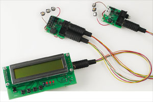
The LEDBUS System
Programmable control for LED lighting
This is a MEMBER ONLY article. You need a subscription to read this article.
- Unlimited access to online Member Only articles
- 3 new editions Elektor Magazine (digital)
- More than 5000 Gerber files
- 20% member discount on e-books (at elektor.com)
- 10% member discount on Products (at elektor.com)
Available from €5.33 per month.
What is Members Only
Elektor is committed to providing high-quality content on electronics, catering to tens of thousands of paying members. As part of this commitment, Elektor has launched Premium, an initiative that offers exclusive online articles to members sometimes even before they appear in the magazine.
Every day, members can access in-depth articles that showcase the best of Elektor's premium content.
This initiative aims to reward members with early access. Once logged in, members can easily enjoy this exclusive content and engage in discussions about featured projects. While Premium adds to the existing resources available, Elektor will continue to provide a wealth of free information.
Join the Elektor community today to take advantage of Premium and other benefits!
Materials
Gerber file
CAM/CAD data for the PCB referred to in this article is available as a Gerber file. Elektor GREEN and GOLD members can exclusively download these files for free as part of their membership. Gerber files allow a PCB to be produced on an appropriate device available locally, or through an online PCB manufacturing service.
Elektor recommends the Elektor PCB Service service from its business partner Eurocircuits or AISLER as the best services for its own prototypes and volume production.
The use of our Gerber files is provided under a modified Creative Commons license. Creative Commons offers authors, scientists, educators and other creatives the freedom to handle their copyright in a more free way without losing their ownership.
Component list
Power module 070459-1
Resistors
R1 = 0Ω33 1 W (SMD 2515)
R2,R3 = 220Ω (SMD 0805)
R4 = 10kΩ (SMD 0805)
Capacitors
C1,C2 = 100nF (SMD 0805)
C3 = 2µF2 (SMD1210; dielectric X7R or X5R)
Semiconductors
D1 = 10BQ100 (Schottky)
D2,D3 = SMD LED (SMD 1206)
T1 = BC850
IC1 = µA78L05ACD
IC2 = MAX491CSD
IC3 = PIC12F638-I/SN, programmed,
IC4 = ZXLD1350ET5CT
Miscellaneous
L1 = 68µH SMD inductor, 10x10; e.g. Epcos B82464G4683M
K1 = 4-way PCB terminal block, lead pitch 5mm
K2 = 6-way SIL pinheader
K3,K5 = 6-way mini-DIN socket, PCB mount
Up to 6 power LEDs; e.g. Luxeon 1W types (see text)
PCB, ref. 070459-1 from www.thepcbshop.com
Project software, free download from www.elektor.de
Central unit 070459-2
Resistors
R1,R2 = 15kΩ
R3,R4,R6 = 4kΩ7
R5 = 33 Ω
R7-R10 = 1kΩ
R11-R14 = 10kΩ
P1 = 10kΩ preset
Capacitors
C1,C2,C4,C5,C6 = 100nF
C3 = 100µF 25V radial
C7,C8 = 22pF
Semiconductors
D1 = 1N4001
D3, D4 = LED 3mm; low-current (D2 omitted)
D5 = LD271; IR-LED
T1 = BC337
IC1 = 7805
IC2 = ATmega32-16PC (SMD), programmed,
IC3 = MAX491CSD
Miscellaneous
S1-S4 = pusbbutton, 6x6 mm
X1 = 16MHz quartz crystal
K4,K6 = 10-way boxheader
K5 = 6-way mini-DIN socket, PCB mount
RC-5 receiver, e.g. SFH5110-36 (on K3)
LCD Module witn 2x20 characters; e.g. Displaytech 202A (on K2)
PCB, ref. 070459-2 from www.thepcbshop.com
Project software and Guide to Operation, free download from www.elektor.de
Discussion (0 comments)
unijerk 7 years ago