

The Secrets of I2C
An I2C bus analyser to let you satisfy your curiosity
This is a MEMBER ONLY article. You need a subscription to read this article.
- Unlimited access to online Member Only articles
- 3 new editions Elektor Magazine (digital)
- More than 5000 Gerber files
- 20% member discount on e-books (at elektor.com)
- 10% member discount on Products (at elektor.com)
Available from €5.33 per month.
What is Members Only
Elektor is committed to providing high-quality content on electronics, catering to tens of thousands of paying members. As part of this commitment, Elektor has launched Premium, an initiative that offers exclusive online articles to members sometimes even before they appear in the magazine.
Every day, members can access in-depth articles that showcase the best of Elektor's premium content.
This initiative aims to reward members with early access. Once logged in, members can easily enjoy this exclusive content and engage in discussions about featured projects. While Premium adds to the existing resources available, Elektor will continue to provide a wealth of free information.
Join the Elektor community today to take advantage of Premium and other benefits!
Materials
Gerber file
CAM/CAD data for the PCB referred to in this article is available as a Gerber file. Elektor GREEN and GOLD members can exclusively download these files for free as part of their membership. Gerber files allow a PCB to be produced on an appropriate device available locally, or through an online PCB manufacturing service.
Elektor recommends the Elektor PCB Service service from its business partner Eurocircuits or AISLER as the best services for its own prototypes and volume production.
The use of our Gerber files is provided under a modified Creative Commons license. Creative Commons offers authors, scientists, educators and other creatives the freedom to handle their copyright in a more free way without losing their ownership.
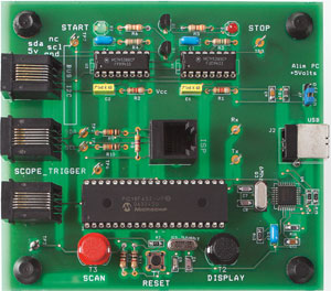
Component list
Resistors
R1,R2 = 8kΩ2
R3,R4 = 1MΩ5
R5,R6 = 330
R7,R13 = 470
R8 = 4kΩ7
R9,R10 = 10k
R11,R12 = 1k
R14,R15 = 27
R16 = 1kΩ5
Capacitors
C1,C2 = 1nF
C3,C4,C10 = 100nF
C5-C8 = 22pF
C9 = 10nF
C11,C12 = 33nF
Semiconductors
D1 = LED, 3mm, red
D2 = LED, 3 mm, green
T1,T2 = 2N7000
IC1,IC2 = 4538
IC3 = PIC18F4520, programmed, Elektor shop item # 070600-41
IC4 = FT232BM (FTDI)
Miscellaneous
K1 = 6-way RJ-11 socket (vertical)
K3,K4,K5 = 6-way RJ-11 socket (horizontal)
L1 = ferrite bead
X1 = 20MHz quartz crystal, HC 49/4H case
X2 = 6 MHz quartz crystal, HC 49/4H case
S1 = miniature pushbutton
S2,S3 = ‘D6’ pushbutton (red and black)
JP1 = 3-way SIL pinheader with jumper
PCB, item # 070600-1
PCB artwork, free download from www.elektor.com
Project software (PC executable and .hex file), item # 070600-11
Discussion (0 comments)