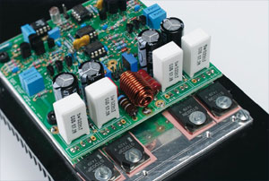
paX: a power amplifier with error correction (2)
The voltage amplifier and input buffer stages

Materials
Gerber file
CAM/CAD data for the PCB referred to in this article is available as a Gerber file. Elektor GREEN and GOLD members can exclusively download these files for free as part of their membership. Gerber files allow a PCB to be produced on an appropriate device available locally, or through an online PCB manufacturing service.
Elektor recommends the Elektor PCB Service service from its business partner Eurocircuits or AISLER as the best services for its own prototypes and volume production.
The use of our Gerber files is provided under a modified Creative Commons license. Creative Commons offers authors, scientists, educators and other creatives the freedom to handle their copyright in a more free way without losing their ownership.
Component list
Resistors
(0.25W metal film)
R1-R4,R6,R8,R17,R18 = 47Ω
R7 = 220Ω
R9,R10,R12,R25,R34 = 4kΩ7
R11 = 249Ω
R13 = 2kΩ74
R16 = 5kΩ23
R19,R20,R30,R31 = 2kΩ15
R21-R24,R60 = 100Ω
R26,R27,R33,R40-R43,R46,R51 = 1kΩ
R28 = 10Ω
R29 = 3kΩ0
R32 = 33Ω
R35,R36 = 619Ω
R37,R38 = 680Ω
R39,R45 = 1MΩ
R44 = 7kΩ5
R47,R48 = 1kΩ8 2W MF
R49,R50 = 10 kΩ
R52-R55 = 0Ω22 5W ceramic
R64 = 1Ω5 2W
R65 = 6(8 2W
RV1, RV2 = 200( multiturn trimmer
R5,R14,R15,R56-R59, R61-R63 = not present
Capacitors
C1,C3,C23 = 150pF polypropylene
C2, C4,C5,C9,C14-C16,C19,C22, C24,C25 = 100nF cer.
C6-C8,C13,C21 = 1µF 63V foil
C10 = 220nF 50V cer.
C11,C12,C17,C18 = 470µF 63V
C26 = 1nF foil
Inductors
L1 = 5µH (see text)
Semiconductors
D1, D2, D5,D6,D10,D11 = zener diode 15V 0.5W
D3,D4,D9,D12,D13,D14 = 1N4148
D7,D8 = 1N4003
Q1,Q2,Q9 = 2SA1208
Q3,Q4,Q10 = 2SC2910
Q5,Q11,Q17,Q18 = BC546B
Q6,Q14,Q19,Q20 = BC556B
Q13,Q16 = STD03N (+ isolation pad & mounting hardware)
Q12,Q15 = STD03P (+ isolation pad & mounting hardware)
U1,U2,U4 = AD844AN
U3 = TL051CP
Miscellaneous
J9 = header 2 x 1 pin (signal input)
J10 = header 2 x 3 pin (+ flatcable)
4 IC sockets DIL08
PCB, ref. 071085-1

Discussion (0 comments)