Article
GPS Receiver

To measure the time taken by the wave to reach it, the GPS receiver compares the transmission time (included in the signal) and reception time of the wave transmitted by the satellite. If the receiver has a clock that is perfectly synchronized with that of the satellites, three satellites are enough to determine the position in three dimensions by triangulation. However, if this is not the case, it takes four satellites to be able to resolve the clock issue and receive the data correctly. A GPS can operate anywhere, just as long as it has an unobstructed view of the sky, 24 hours a day, 7 days a week. However, it’s important to be aware that the position data may be incorrect in the presence of electromagnetic interference.
Materials
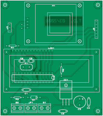
Component list
Resistors
R1 = 1kOhm5
R2,R3 = 10kOhm
Capacitors
C1 = 100nF
C2,C4 = 470nF
C3 = 100µF 16V
C5,C6 = 22pF
Semiconductors
D1 = 1N4007
IC1 = 7805 (TO220 case)
IC2 = PIC16F876A (20 MHz), programmed with hex file from archive 080238-11.zip
Miscellaneous
X1 = 20 MHz quartz crystal (low profile)
JP1,S1,S2= 2-pin connector, 5mm lead pitch
J2 = 6-way SIL pinheader
J3 = 3-way SIL pinheader
K1 = connector for 9V battery
LCD1 = LCD, 2x16 characters, e.g. LM016L or equivalent
M1 = GPS receiver module type 28146 (Parallax Inc.)
PCB, ref. 080238-1 from www.thepcbshop.com


Discussion (0 comments)