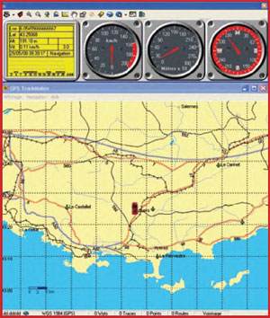
Multi-purpose GPS Receiver
For those who are keen to know everything!

This is a MEMBER ONLY article. You need a subscription to read this article.
- Unlimited access to online Member Only articles
- 3 new editions Elektor Magazine (digital)
- More than 5000 Gerber files
- 20% member discount on e-books (at elektor.com)
- 10% member discount on Products (at elektor.com)
Available from €5.33 per month.
What is Members Only
Elektor is committed to providing high-quality content on electronics, catering to tens of thousands of paying members. As part of this commitment, Elektor has launched Premium, an initiative that offers exclusive online articles to members sometimes even before they appear in the magazine.
Every day, members can access in-depth articles that showcase the best of Elektor's premium content.
This initiative aims to reward members with early access. Once logged in, members can easily enjoy this exclusive content and engage in discussions about featured projects. While Premium adds to the existing resources available, Elektor will continue to provide a wealth of free information.
Join the Elektor community today to take advantage of Premium and other benefits!
Materials
Gerber file
CAM/CAD data for the PCB referred to in this article is available as a Gerber file. Elektor GREEN and GOLD members can exclusively download these files for free as part of their membership. Gerber files allow a PCB to be produced on an appropriate device available locally, or through an online PCB manufacturing service.
Elektor recommends the Elektor PCB Service service from its business partner Eurocircuits or AISLER as the best services for its own prototypes and volume production.
The use of our Gerber files is provided under a modified Creative Commons license. Creative Commons offers authors, scientists, educators and other creatives the freedom to handle their copyright in a more free way without losing their ownership.
Component list
Capacitors
C1 = 470µF 25 V radial
C2 = 220nF MKT
C3 = 10µF 25 V radial
C4-C9 = 100nF ceramic
Semiconductors
D1 = 1N4004
IC1 = 78L05
IC2 = GPS receiver type EM-406A (see text)
IC3 = MAX242 (Maxim IC)
Miscellaneous
K1 = PCB mount DC adaptor socket
K2 = 6-way SIL pinheader
K3 = 9-way sub-D socket (female), PCB mount
K4 = connector type SM06B-SRSS-RB (Digikey)
K5 = 4-way SIL pinheader
JP1 = 3-way SIL pinheader with jumper
PCB copper track layout, free download # 070309-1 from www.elektor.com
Comprehensive Autonomous GPS Receiver
Resistors (0.25W / 5%)
R1 = 100Ohm
R2-R5 = 10kOhm
R6 = 220Ohm
R7 = 0Ohm*
Capacitors
C1 = 100µF 25V radial
C2 = 47µF 25V radial
C3 = 10nF ceramic
C4,C5 = 22pF ceramic
Semiconductors
LCD1 = alphanumeric LCD, 4 lines of 20 characters
IC1 = LT1300
IC2 = PIC18F2520, programmed, Elektor SHOP # 080309-41
IC3 = 74LS04
D1 = 1N5817 (must be Schottky)
D2 = 5.1V or 5.6V 400 mW zener diode
Miscellaneous
L1 = 22 µH, Panasonic type ELC08D (e.g. RS Components)
Qz1 = 20MHz quartz crystal
P1 = 10kOhm preset H
K1-K4 = 2-way SIL pinheader
K5 = DC adaptor socket
K6 = 4-way SIL pinheader
K7 = connector type SM06B-SRSS-TB(LF)(SN) (Digikey)
Type EM-406A GPS receiver (see text)
PCB copper track layout, free download # 070309-2 from www.elektor.com


Discussion (0 comments)