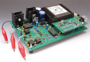
Transistor Curve Tracer
On USB, for bipolar trannies and FETs

Materials
Gerber file
CAM/CAD data for the PCB referred to in this article is available as a Gerber file. Elektor GREEN and GOLD members can exclusively download these files for free as part of their membership. Gerber files allow a PCB to be produced on an appropriate device available locally, or through an online PCB manufacturing service.
Elektor recommends the Elektor PCB Service service from its business partner Eurocircuits or AISLER as the best services for its own prototypes and volume production.
The use of our Gerber files is provided under a modified Creative Commons license. Creative Commons offers authors, scientists, educators and other creatives the freedom to handle their copyright in a more free way without losing their ownership.
Extra info / Update
Quick Project Specs
- R8C/13 microcontroller control module
- PC link via USB port
- User-friendly PC program with Help function (runs under Windows 2000 and XP)
- Curve data can be exported to and imported from Excel
- Checking transistor matching
- Records characteristic curves of NPN and PNP transistors, N-channel and P-channel MOSFETs, and N-channel and P-channel JFETs
- Plotted curves can be printed out or embedded in other applications
Corrections
The circuit diagram does not show the link between pin 11 of K1 and pin 22 of the R8C/13 module. The PCB for the project is not affected.
In the circuit diagram (Figure 2, section a), the bussed connection between pin 22 (P3.0) of the R8C/13 module and resistor R24 is missing. This connection is however present on the circuit board, for which no modification is required.
In the component list, transistor T2 should be a type BC557A, not BC547A. No modification is required to the PCB or the schematic.
Component list
Resistors
R1 = 1kO5, SMD 0603
R2,R3 = 27O, SMD 0603
R4,R10,R11,R14-R28 = 470O, SMD 0603
R5,R6,R7 = 220kO, SMD 0603
R8,R9,R12,R29,R30,R31 = 4kO7, SMD 0603
R13 = 1kO, SMD 0603
Capacitors
C1,C2,C4,C8,C9,C11,C13 = 100nF, SMD 0603
C3,C12 = 22pF, SMD 0603
C5,C6 = 10pF, SMD 0603
C7,C10 =10µF 25V, SMD case A
Semiconductors
D1 = LL4148
D2 = LED, 3mm, low-current
IC1 = PL2303X
IC2 = R5F21134FP (R8C/13)
Miscellaneous
K2 = USB-B socket
K1 = 20-way (2x10) DIL pinheader
S1 = pushbutton, 6mm, SMD
X1 = 20 MHz quartz crystal, SMD
X2 = 12 MHz quartz crystal, SMD
JP1 = 2-way SIL pinheader with jumper
F1 = 100 mA Polyfuse
Main board # 080068-1
Resistors
R1-R18,R24-R33,R37,R38,R41-R45,R48,R51,R52,R53 = 10kO
R19,R20,R22 = 4kO7
R21 = 931kO
R23 = 88kO7
R34,R35 = 1O5
R36 = 100O
R39,R40,R46,R47 = 20kO
R49 = 1O 1W
R50 = 90kO9
Capacitors
C1,C2 = 2200µF 35V radial
C3-C6,C11,C12,C14-C17,C19-C35 = 100nF, lead pitch 2.5mm
C7-C10 = 10µF 25V radial
C13,C18 = 47nF, lead pitch 2.5mm
C36,C37 = 22nF, lead pitch 2.5mm
Semiconductors
D1-D4,D6,D7 = 1N4148
D5,D8 = 5.6 V 500 mW zener diode
D9-D12 = LED, low-current, 3 mm
B1 = VM18, bridge rectifier 1 A / 100 V, DIP4
T1,T2 = BC547A
T3 = BD139
T4 = BD140
IC1 = 7812
IC2 = 7815
IC3 = 7915
IC4 = 7912
IC5,IC6,IC8,IC11,IC12 = TL082P
IC7,IC9 = DG441DJ
IC10, IC13 = TL081P
Miscellaneous
K1 = 20-way DIL socket
K2 = 3-way PCB terminal block, lead pitch 2.5mm
F1 = 100 mAT (slow) glass fuse, with holder
TR1 = mains transformer, secondary 2x 15V / 14VA
4 heatsinks type FK218/SA32 (21 K/W)
Microcontroller and PC Software: free download 080068-11.zip at [3].
PCBs 080068-1 and 080068-2, available from the Elektor Shop.
Controller board also with components fitted, Elektor Shop # 080068-91.


Discussion (0 comments)
joicol 4 years ago
David Sapsford 1 year ago
Ewan Cameron 4 years ago
Heitor Alves Heitor Alves 6 months ago
Content Director, Elektor 5 months ago
Jürgen Kellers 6 months ago
- The software is for Win 2000/XP which is obsolete
- Two PCB make the device unnecessarily expensive.
- Is a linear power supply required? Wouldn't a small switch-mode power brick (e.g., Meanwell) be cheaper and more compact? Also, the PCB would be get cheaper.
- The prolific PL 2303 UART is phased out. My suggestion is to abandon the upper PCB and use a FTDI UART for 5€ altogether. Or even abandon the dedicated UART which gets me to the last point.
- The microcontroller is also obsolete, and replaced by the RL78/G14 family. I am definitively not familiar with this make of microcontrollers. Can a ESP8266 be used instead? For small cash this would come with its own PCB, integrated UART and USB connector.
Just my 5 cents...Have a great day all!pbaak 6 months ago