Experimenting with the MSP430
Low-cost development system with a USB interface
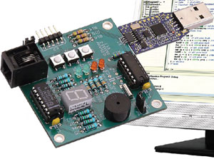
Texas Instruments supplies handy USB evaluation sticks with related software for its low-cost MSP430 controllers. Unfortunately the I/O facilities are somewhat limited. These can be substantially enhanced with the help of the experimenter’s board described here. This combination forms the hardware basis for a mini-course ‘Starting with embedded C’, which can be found elsewhere in this issue.
Sometimes several initiatives converge at just the right time to create a new concept. For some time Rotterdam University had been looking for a low-cost development system for its students in Automotive and Electronic Engineering, which could be put to use in microcontroller tuition. In addition, for logistical reasons Elektor was looking for a more practical replacement for the very popular E-blocks for its Embedded C Programming workshops. So both Rotterdam University and Elektor were effectively looking for the same thing, although for different reasons.
Materials
Gerber file
CAM/CAD data for the PCB referred to in this article is available as a Gerber file. Elektor GREEN and GOLD members can exclusively download these files for free as part of their membership. Gerber files allow a PCB to be produced on an appropriate device available locally, or through an online PCB manufacturing service.
Elektor recommends the Elektor PCB Service service from its business partner Eurocircuits or AISLER as the best services for its own prototypes and volume production.
The use of our Gerber files is provided under a modified Creative Commons license. Creative Commons offers authors, scientists, educators and other creatives the freedom to handle their copyright in a more free way without losing their ownership.
Extra info / Update
Specifications
• Experimenter’s board with several I/O possibilities
• Powerful 16-bit MSP430F2012 controller running at 16 MHz, 2 KB Flash and 128 bytes RAM
• 4 indicator LEDs
• 7-segment display
• Piezo buzzer
• Three pushbuttons
• I2C/SPI connector
• Powered via the USB stick or an external adapter
Component list
Resistors
R1-R8 = 150? 0.25W
R9-R12 = 330? 0.25W
R13-R16 = 47k? 0.25W
Capacitors
C1,C2 = 100nF
C3,C4 = optional, not fitted here (see TI Appl. Report SLAA322)
Semiconductors
D1,D2 = low-current LED, red, diam. 3mm
D3,D4 = low-current LED, green, diam. 3mm
LD1 = 7-segment LED display, common cathode (e.g. Lite-On LTS4301E)
IC1 = 74HC4094
IC2 = MSP430F2012IN (TI)
Miscellaneous
S1,S2,S3 = PCB mount pushbutton, 5x5mm (e.g. Tyco FSM4JH)
K1 = right angled 4-pin connector, lead pitch 1.27mm (Mill-Max # 851-93-004-20-001000)
K2 = 6-way RJ11 connector, PCB mount (Molex # 95009-2661)
K3 = 5-way SIL pinheader
JP1,JP2 = 3-way pinheader and jumper
BZ1 = passive piezo buzzer (e.g. Kingstate# KPEG242)
X1 = 32.768kHz quartz crystal
16-pin IC socket for IC1
14-pin IC socket for IC2
PCB, # 080558-2
Ready assembled and tested board: Elektor Shop # 080558-91
TI eZ430-F2013 evaluation kit: Elektor Shop # 080558-92
Discussion (0 comments)