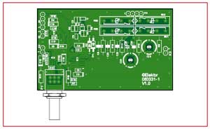
True RMS Digital Voltmeter
with frequency counter

Materials
Gerber file
CAM/CAD data for the PCB referred to in this article is available as a Gerber file. Elektor GREEN and GOLD members can exclusively download these files for free as part of their membership. Gerber files allow a PCB to be produced on an appropriate device available locally, or through an online PCB manufacturing service.
Elektor recommends the Elektor PCB Service service from its business partner Eurocircuits or AISLER as the best services for its own prototypes and volume production.
The use of our Gerber files is provided under a modified Creative Commons license. Creative Commons offers authors, scientists, educators and other creatives the freedom to handle their copyright in a more free way without losing their ownership.
Extra info / Update
Main Characteristics
- Four measurement ranges: 0.1 V, 1 V, 10 V, 100 V
- Voltmeter bandwidth: 20 Hz to 1 MHz (basic accuracy ±1.0 % of full scale)
- Frequency counter bandwidth: 1 Hz to 10 MHz (typ.), 25 MHz (max.) (±timebase error)
- Minimum input voltage for counter: approximately 50 mVRMS
- Input impedance: = 1 MO || = 50 pF
- Counter timebase: 100 ms, 1 s
- Adjustable trigger level: approximately ±0.15 V
- Autoranging (may be disabled)
- Offset correction and calibration facility
- Automatic scaling of frequency display
- Voltage displayed as RMS value or peak-to-peak value (for sinusoidal input)
- Crest factor: =4
- Two measurement inputs
Component list
Measurement Amplifier
Resistors
R1,R2, R5 = 47Ohm (SMD 0805)
R3,R4 = 27Ohm (SMD 0805)
R6 = 100k
R7 = 10k (SMD 0805)
R8 = 470kO (SMD 0805)
R9 = 900kO 0.1%
R10,R11 = 4kO7
R12 = 90kO 0.1%
R13 = 9kO 0.1%
R14 = 1kO 0.1%
R15 = 430Ohm (SMD 0805)
R16 = 430Ohm (SMD 1206)
R17 = 4kO7 (SMD 0805)
R18 = 4kO7 (SMD 0805)
P1 = 10kO (Alps type 290061)
Capacitors
C1,C2,C11,C13,C16,C19 = 100nF (SMD 0805)
C3,C4,C10,C12 = 4µF7 10V (293D/A)
C5,C6 = 10nF (SMD 0805)
C7 = 27pF (SMD 0805)
C8 = 10nF
C9 = 1nF (SMD 0805)
C14 = 1µF 10V (SMD 0805)
C15 = 10µF 10V (SMD 0805)
C17,C18 = 10µF 10V (293D/A)
C20,C21 = 2.5-35pF trimmer (C-TRIMM808-7.5)
C22 = 2nF2
C23 = 22nF
C24,C25 = 220pF
Semiconductors
IC1= ADA4862-3 (SMD)
IC3 = LTC1968CMS8 (MSOP-8)
IC4 = LT1016CS8 (SO-8)
D1,D2 = BAS45 (1N4148)
D3,D4 = BZW55-2.7 (SMD)
T1 = Dual FET PMBFJ620 (NXP)
Miscellaneous
Re1–Re4 = SIL7271-L 5V or MEDER SIL05-IA72-7ID
K1,K2,K3 = 2-way pinheader
K4,K5 = 4-way pinheader
2x SMA case socket
Metal case e.g. TEKO # 372
BNC case socket
Miniature rocker switch
7x 1nF feedthrough capacitor
PCB # 080331-1, see www.elektor.com/shop
Display board
Resistors
R3,R5 = 10kO (SMD 0603)
R4 = 10k
R6 = 33k (SMD 0603)
R7 = 4kO7 (SMD 0603)
R8 = 100kO (SMD 0603)
R11,R12,R13,R14 = 1kO (SMD 0805)
R15 = 1kO (SMD 0603)
Capacitors
C2,C4 = 1µF 10V (SMD 0603)
C3,C6,C7 = 100nF (SMD 0603)
C5 = 4µF7 10V (SMD 0603)
C8 = 18pF (SMD 0603)
C9 = 27pF (SMD 0603)
C10= 20pF trimmer (C-TRIMMCTZ3)
Semiconductors
IC1 = R8C13 (R5F21134FP, LQFP32) IC2 = LTC2420CS8 (SO-8)
IC3 = LT1790ACS6-2.048 (SOT23-6)
D1..D4 = 1N4148 (SOD-323)
T1 = BC558C (SOT-23)
T2–T6 = 2N7002 (SOT-23)
LED1–LED4 = LED, green (SMD 1206)
LED5 = LED, 3mm
Miscellaneous
LCD1 = LCD 2×16
JP1 = 2-way pinheader and jumper
K1,K2,K3 = 2-way pinheader
K4,K5 = 4-way pinheader
X1 = 20MHz quartz crystal, HC-49US12SMD
S1-S4 = pushbutton (Schurter # 1241.1614)
S5 = pushbutton (6mm)
PCB # 080331-2, see www.elektor.com/shop


Discussion (0 comments)
Andreas Lieb 2 months ago
Beim Versuch den Originalartikel aus meinem Elektor Archiv zu öffnen, stellte ich fest, daß dieser - zumindest im 2009 - nicht zu finden ist.
DE0163590ID 2 months ago
Hans Grilnberger 2 months ago