

OBD Analyser NG
Next-generation handheld with graphical display, ARM Cortex M3 controller and Open Source user interface
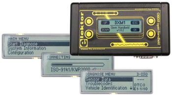
The compact OBD2 Analyser in the June 2007 issue was an enormous success — not surprising for an affordable handheld onboard diagnostics device with automatic protocol recognition and error codes explained in plain language. Now enhanced with a graphical display, Cortex M3 processor and an Open Source user interface, the next generation of Elektor’s standalone analyser sets new standards for a DIY OBD2 project.
This is a MEMBER ONLY article. You need a subscription to read this article.
- Access to Elektor archive and 5,000+ Gerber files
- Receive up to 8 magazines per year (digital and/or paper)
- 10% discount in the Elektor store
Available from €4.95 per month.
What is Members Only
Elektor is committed to providing high-quality content on electronics, catering to tens of thousands of paying members. As part of this commitment, Elektor has launched Premium, an initiative that offers exclusive online articles to members sometimes even before they appear in the magazine.
Every day, members can access in-depth articles that showcase the best of Elektor's premium content.
This initiative aims to reward members with early access. Once logged in, members can easily enjoy this exclusive content and engage in discussions about featured projects. While Premium adds to the existing resources available, Elektor will continue to provide a wealth of free information.
Join the Elektor community today to take advantage of Premium and other benefits!
Materials
Extra info / Update
Hardware Handheld Analyser:
• Full graphics display 132 x 32 pixels
• RGB backlighting
• Convenient four press button control
• Power supply taken from onboard diagnostics port (12 V car battery)
• Uses standard OBD cable
• Convenient size (126 mm wide x 68 mm tall x 25 mm deep)
• Weight approx. 110 g
Hardware and software DX module (DXM-PCB):
• Hardware for onboard OBD2 control
• Firmware for onboard OBD2 control
• 3V3 tx-rx level
• Cortex M3 CPU (32-bit controller)
• 72 MHz internal clock rate
• Onboard 3V3 power supply for external device – max. 55mA
• Jumperless
• Bootloader
• LED indicators for onboard Connect and Data Stream
• Analogue battery voltage measurement
• AT control set
• Supports all currently implemented protocols: PWM, VPWM, ISO9141-2, ISO14230-4 (KWP2000), ISO15765-4 (CAN, 11/29 Bit , 250/500 kBaud)
• Firmware update via ISP interface
• Rapid OBD connection
Open Source firmware functions:
• Graphical user control interface display
• Selection of vehicle data, PID list, error code list, VIN, MIL status
• Selection menu for active transmission control system (for vehicles with multiple transmission options, e.g. automatic gearbox)
• Saved error store (freeze-frames) for previous faults
• Expandable memory bank for sample error codes
• Erasable error store
• Live display of sensor data
• Acoustic signals
• Selection menu for scan mode (automatic or manual)
• Menu text in English
• Choice of direction (rotatable through 180 degrees)
• Controllable RGB backlight brightness
• Battery voltage measurement
Expansion options:
• USB port for data transfer or supporting use with PC
• Real-time clock (RTC) for data recording (e.g. time and date stamping)
• Adequate checklist flash memory (1, 2 or 4 MByte) for data logging functions
Open Source:
• Open Source firmware for the controller
• ISP interfaces accessible for AT90CAN128 and AT90USB162
• Other firmware can be substituted if required
• Demo firmware for ‘Speedometer with warning functions’
Component list
C1,C2 = 22pF
C3,C4 = 100nF
C5,C6,C11–C18 = 1µF
R1 = 10kOhm
R2,R3 = 1Ohm
R4 = 1kOhm
R5,R6 = 1.5kOhm
R7,R10,R13 = 110Ohm
R8,R11,R14 = 68Ohm
R9,R12,R15 = 47Ohm
R16 = 330Ohm
R17 = 33Ohm
R18,R19 = 4.7kOhm
Q1 = 8MHz quartz crystal
D1 = 1N4007
D2 = B0530WS
D3 = 1N4148
T1,T2,T3 = BCR108
IC1 = LD1117 3V3
IC2 = MC34063
IC3 = AT90CAN128
LED1,LED2,LED3 = RGB LED, Kingbright type KAA-3528SURKVGAPBA
Components to be fitted separately:
DSP1 = LCD 132 x 32
DXM = OBD module
J1,J2 = 10-way SIL pinheader
J3 = 2-way pinheader
L1 = 220µH (choke coil)
LS1 = miniature loudspeaker
S1–S4 = pushbutton
SV1 = 10-way boxheader
X1 = 9-pin sub-D plug with solder buckets
Fastenings and accessories:
4 x pushbutton plungers
4 x case screws
5 x PCB screws
Diffuser
Cardboard packaging
Case with front panel
Sub-D connector fixings
Standard OBD2 cable
Sources of supply:
Component set # 090451-71 available from the Elektor Shop contains all necessary components and the PCB with SMD components pre-fitted together with the case (with custom front overlay), fixings and the standard OBD2 cable. See Elektor Shop pages.
Discussion (0 comments)