

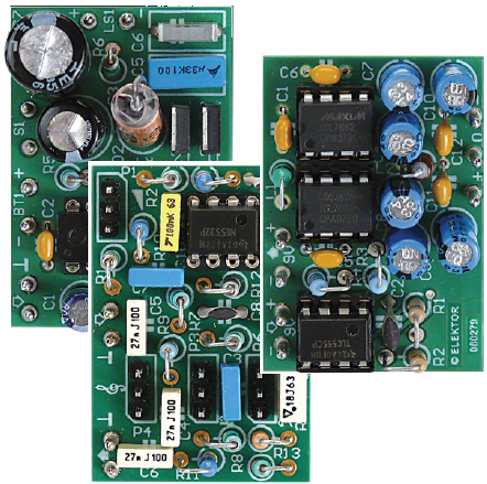
Pocket Preamp, part 2
A simple preamplifier with tone control
This is a MEMBER ONLY article. You need a subscription to read this article.
- Access to Elektor archive and 5,000+ Gerber files
- Receive up to 8 magazines per year (digital and/or paper)
- 10% discount in the Elektor store
Available from €4.95 per month.
What is Members Only
Elektor is committed to providing high-quality content on electronics, catering to tens of thousands of paying members. As part of this commitment, Elektor has launched Premium, an initiative that offers exclusive online articles to members sometimes even before they appear in the magazine.
Every day, members can access in-depth articles that showcase the best of Elektor's premium content.
This initiative aims to reward members with early access. Once logged in, members can easily enjoy this exclusive content and engage in discussions about featured projects. While Premium adds to the existing resources available, Elektor will continue to provide a wealth of free information.
Join the Elektor community today to take advantage of Premium and other benefits!
Gerber file
CAM/CAD data for the PCB referred to in this article is available as a Gerber file. Elektor GREEN and GOLD members can exclusively download these files for free as part of their membership. Gerber files allow a PCB to be produced on an appropriate device available locally, or through an online PCB manufacturing service.
Elektor recommends the Elektor PCB Service service from its business partner Eurocircuits or AISLER as the best services for its own prototypes and volume production.
The use of our Gerber files is provided under a modified Creative Commons license. Creative Commons offers authors, scientists, educators and other creatives the freedom to handle their copyright in a more free way without losing their ownership.
Extra info / Update
Main Specifications
- 3-band tone control
- Symmetrical supply
- Compact
- Connector layout matched to associated boards
Component list
Resistors
R1 = 220kOhm
R2 = 3.3kOhm
R3 = 10kOhm
R4,R5 = 2.2k
R6 = 15kOhm
R7,R8 = 1.5kOhm
R9 = 4.7kOhm
R10,R11 = 1kOhm
R12 = 1MOhm
R13 = 100Ohm
P1 = 10kOhm potentiometer, logarithmic
P2,P3,P4 = 10kOhm potentiometer, linear
Capacitors
(lead pitch 5mm / 0.2")
C1,C8 = 68pF ceramic
C2 = 180nF polyester / MKT
C3 = 4.7nF polyester / MKT
C4,C5,C6 = 27nF polyester / MKT
C7 = 6.8nF polyester / MKT
C9,C10 = 100nF polyester / MKT
Semiconductors
IC1 = NE5532 (DIP-8)
Miscellaneous
PCB, # 080278-1, from www.thepcbshop.com
Power supply board
Resistors
R1,R2 = 100kOhm
R3,R4 = 1kOhm
Capacitors
C1,C5,C6,C11,C12 = 100nF ceramic, lead pitch 5mm (0.2'')
C2 = 100pF, lead pitch 5mm (0.2'')
C3,C4,C9,C10 = 10µF 63V radial electrolytic, lead pitch 2.5mm (0.1'')
C7,C8 = 4.7µF 63V radial electrolytic, lead pitch 5mm (0.2'')
Inductors
L1 = 10µH axial (vertical mounting)
L2 = 1mH axial (vertical mounting)
Semiconductors
IC1 = TLC555 (DIP-8)
IC2,IC3 = ICL7662CPA+ (DIP-8) (Maxim IC)
Miscellaneous
PCB # 080279-1 from www.thepcbshop.com
Discussion (0 comments)