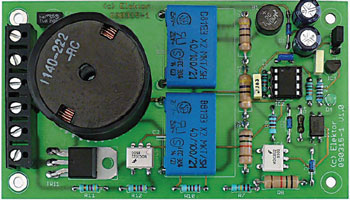
Dimmer with a Micro
For incandescent and halogen lamps up to 300 watts

Dimmers come in many varieties — you’d think. Still, the author did not find what he wanted. So it was back to the drawing board to design a dimmer circuit with the exact personal requirements. The result is a project that’s easy to add to the existing electrical installation as well as simple to operated using existing light switches. The design is for 230 V, 50 Hz AC power lines and our US and Canadian readers are expressly invited to rework it to 110/115 VAC, 60 Hz.
This is a MEMBER ONLY article. You need a subscription to read this article.
- Unlimited access to online Member Only articles
- 3 new editions Elektor Magazine (digital)
- More than 5000 Gerber files
- 20% member discount on e-books (at elektor.com)
- 10% member discount on Products (at elektor.com)
Available from €5.33 per month.
What is Members Only
Elektor is committed to providing high-quality content on electronics, catering to tens of thousands of paying members. As part of this commitment, Elektor has launched Premium, an initiative that offers exclusive online articles to members sometimes even before they appear in the magazine.
Every day, members can access in-depth articles that showcase the best of Elektor's premium content.
This initiative aims to reward members with early access. Once logged in, members can easily enjoy this exclusive content and engage in discussions about featured projects. While Premium adds to the existing resources available, Elektor will continue to provide a wealth of free information.
Join the Elektor community today to take advantage of Premium and other benefits!
Materials
Gerber file
CAM/CAD data for the PCB referred to in this article is available as a Gerber file. Elektor GREEN and GOLD members can exclusively download these files for free as part of their membership. Gerber files allow a PCB to be produced on an appropriate device available locally, or through an online PCB manufacturing service.
Elektor recommends the Elektor PCB Service service from its business partner Eurocircuits or AISLER as the best services for its own prototypes and volume production.
The use of our Gerber files is provided under a modified Creative Commons license. Creative Commons offers authors, scientists, educators and other creatives the freedom to handle their copyright in a more free way without losing their ownership.
Extra info / Update
Features
- Dimmer function using phase angle control
- Simple to set (can also be permanently set)
- Suitable for two-way switch circuits (staircase circuit)
- very low profile construction (20 mm)
- transformerless
Component list
Resistors
R1,R2 = 470? 1W
R3, R13 = 15k?
R4 = 10k?
R5 = 1k?
R6,R8 = 15k? 1W
R7 = 220k?
R9,R10 = 820?
R11,R12 = 470?
Capacitors
C1,C2 = 220nF 250V, polypropylene, X2 class
C3,C4 = 220µF 35V, radial, lead pitch 3.5mm
C5,C6,C7 = 100nF, ceramic, lead pitch 5mm
Semiconductors
B1 = W06M, bridge rectifier, 1.5A, 600Vpiv, (e.g. Farnell # 1621776)
D1 = 16V 0.5W zener diode
D2,D3 = 6.2V 0.5W zener diode
D4 = LED, low-current, green, 3mm
IC1 = 78L05 (TO-92 case)
IC2 = PIC12F629A (Microchip), DIL8 case, programmed, Elektor Shop # 090315-41
IC3 = SFH620A-3 optocoupler (e.g. Farnell # 1469594)
IC4,IC5 = MOC3022 optocoupler (e.g. Farnell # 1021366)
TRI1 = BTA08-600BRG, triac, 8A, 600V, TO-220AB case (e.g. Farnell # 1057269)
Miscellaneous
F1 = 1.6 A (slow blow) subminiature, (e.g. DigiKey # 507-1178-ND)
K1 = AK110/6wp, 6-way terminal block, lead pitch 7.5mm
K2 = 3-pin SIL header lead pitch 2.54mm, with jumper
L1 = 2.2mH suppressor coil, (e.g. DigiKey # M8383-ND or Conrad Electronics # 534358-89)
2 pcs DIL6 IC socket
PCB # 090315-1


Discussion (0 comments)