

Multi Function Switch
Smart Switch for power line AC
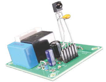
With this smart switch you can turn mains-powered devices on and off easily and conveniently. Applications such as TVs, radios, basement and outside lights and the like come to mind. Thanks to various sensor options this can also be done automatically or with a delay. In addition, this circuit also helps to save energy.
This is a MEMBER ONLY article. You need a subscription to read this article.
- Unlimited access to online Member Only articles
- 3 new editions Elektor Magazine (digital)
- More than 5000 Gerber files
- 20% member discount on e-books (at elektor.com)
- 10% member discount on Products (at elektor.com)
Available from €5.33 per month.
What is Members Only
Elektor is committed to providing high-quality content on electronics, catering to tens of thousands of paying members. As part of this commitment, Elektor has launched Premium, an initiative that offers exclusive online articles to members sometimes even before they appear in the magazine.
Every day, members can access in-depth articles that showcase the best of Elektor's premium content.
This initiative aims to reward members with early access. Once logged in, members can easily enjoy this exclusive content and engage in discussions about featured projects. While Premium adds to the existing resources available, Elektor will continue to provide a wealth of free information.
Join the Elektor community today to take advantage of Premium and other benefits!
Materials
Gerber file
CAM/CAD data for the PCB referred to in this article is available as a Gerber file. Elektor GREEN and GOLD members can exclusively download these files for free as part of their membership. Gerber files allow a PCB to be produced on an appropriate device available locally, or through an online PCB manufacturing service.
Elektor recommends the Elektor PCB Service service from its business partner Eurocircuits or AISLER as the best services for its own prototypes and volume production.
The use of our Gerber files is provided under a modified Creative Commons license. Creative Commons offers authors, scientists, educators and other creatives the freedom to handle their copyright in a more free way without losing their ownership.
Component list
Resistors
R1-R4 = 100kOhm (SMD 1206)
R5 = 100kOhm (SMD 0805)
R6,R9 = 22kOhm (SMD 0805)
R7 = 100Ohm (through-hole)
R8 = 1kOhm (SMD 0805)
Inductors
L1 = 47µH, e.g. Panasonic ELJFA470JF (1210 suppressor coil, min. 80mA)
Capacitors
C1,C6,C9,C10 = 100nF (SMD 0805)
C2,C5 = 10n (SMD 0805)
C3,C4 = 220nF 275VAC X2
C7 = 100µF 35V radial
C8 = 10µF 35V radial
Semiconductors
D1-D8 = TS4148
D9 = 24V 1.5W zener diode
D10 = LED 0805
T1 = MMBF170
IC1 = PIC10F206T-I/OT
IC2 = L78L05ABD
Miscellaneous
Re1 = 24VDC relay, SPST, Multicomp type HRS4-S DC24V
K1 = 5-way SIL pinheader
K2 = 3-way PCB screw terminal block, lead pitch 7.5mm
With the Twilight and IR switch, components R2, R4, C4, D5 and D7 are omitted
Twilight switch
R10 = LDR FW200, Conrad Electronics # 183580
R11 = 1k
P1 = 250k
C11 = 10µF 63V
C12 = 100nF
IR switch
IC3 = IR switch, TSOP1738
C13 = 100nF
Countdown switch (R1,R3 and C3 omitted)
S1 = pushbutton, 1 make contact (see text)
R12,R13 = 5kOhm6 1W
Discussion (0 comments)