

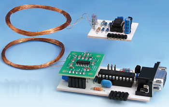
Wireless Electricity meets RFID
Do-it-yourself wireless RFID sensor systems
This is a MEMBER ONLY article. You need a subscription to read this article.
- Unlimited access to online Member Only articles
- 3 new editions Elektor Magazine (digital)
- More than 5000 Gerber files
- 20% member discount on e-books (at elektor.com)
- 10% member discount on Products (at elektor.com)
Available from €5.33 per month.
What is Members Only
Elektor is committed to providing high-quality content on electronics, catering to tens of thousands of paying members. As part of this commitment, Elektor has launched Premium, an initiative that offers exclusive online articles to members sometimes even before they appear in the magazine.
Every day, members can access in-depth articles that showcase the best of Elektor's premium content.
This initiative aims to reward members with early access. Once logged in, members can easily enjoy this exclusive content and engage in discussions about featured projects. While Premium adds to the existing resources available, Elektor will continue to provide a wealth of free information.
Join the Elektor community today to take advantage of Premium and other benefits!
Materials
Gerber file
CAM/CAD data for the PCB referred to in this article is available as a Gerber file. Elektor GREEN and GOLD members can exclusively download these files for free as part of their membership. Gerber files allow a PCB to be produced on an appropriate device available locally, or through an online PCB manufacturing service.
Elektor recommends the Elektor PCB Service service from its business partner Eurocircuits or AISLER as the best services for its own prototypes and volume production.
The use of our Gerber files is provided under a modified Creative Commons license. Creative Commons offers authors, scientists, educators and other creatives the freedom to handle their copyright in a more free way without losing their ownership.
Extra info / Update
- standard microcontroller (ATtiny2313)
- works with EM4102-compatible RFID tags
- output over RS232 interface
DIY and sensor RFID tags:
- standard microcontroller (ATtiny13)
- EM4102 compatible
- analogue and digital inputs for sensors
- status and readings transmitted via RFID ID
- separate adaptor board for programming and debugging
Open source software collection:
- RFID reader firmware
- DIY RFID tag firmware for:
standard RFID tag (fixed ID)
RFID tag with alternating ID
RFID tag with switchable ID
RFID tag with configurable ID
RFID tag with two analogue inputs
RFID tag with temperature sensor
Component list
(PCB # 100051-1)
Resistors
R1 = 1kOhm
R2 = 4.7kOhm
R3 = 330Ohm
Capacitors
C1 = 1.7nF (see text)
C2 = 10µF 25V
C3 = 100µF 25V
Inductor
L1 = 1mH (see text)
Semiconductors
D1–D4 = BAT43
IC1 = ATTiny13-20PU, programmed, Elektor # 100051-41*
Miscellaneous
K1 = 6-way right-angled pinheader
PCB # 100051-1*
Programmer / Debug Adapter
(PCB # 100051-2)
Capacitors
C1 = 100nF
Semiconductors
IC1 = ATTiny13-20PU (for programming / debugging)
Miscellaneous
K1 = 6-pin (2x3) pinheader
K2 = 5-pin right-angled pinheader
K3 = 6-pin right-angled pinheader
PCB # 100051-2*
RFID Reader
(PCB # 100051-3)
Resistors
R1,R2,R3 = 1kOhm
R4 = 2.2kOhm
Capacitors
C1,C3 = 100nF
C2 = 100µF 25V
C4 = 10µF 25V
Semiconductors
D1 = LED, 3mm, red
D2 = 1N4007
IC1 = ATTiny2313-20PU, programmed, Elektor # 100051-42*)
IC2 = 78L05
X1 = 8MHz ceramic resonator
T1 = BS170
Inductor
L1 = 1 mH (see text)
Miscellaneous
K1 = 6-pin (2x3) pinheader
K2 = 9-way sub-D socket, right-angled pins, PCB mount
K3 = 5-way SIL socket
K4 = 5-way SIL socket, right-angled pins
K5 = DC adapter socket, PCB mount, for plug diam. 2.1 mm
RFID module # 080910-91* (SMD stuffed EM4095 board)
PCB # 100051-3*
* Kit of parts, order code 100051-71. Contains RFID module # 080910-91, PCBs # 100051-1, -2 und -3 and programmed microcontrollers # 100051-41 and -42
Discussion (0 comments)