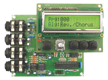
Digital Multi-Effects Unit
With 15 configurable sound effects and a user-friendly HMI

It’s a simple fact: every recording sounds better with the right sound effects. Here we prove that it’s possible to generate a variety of effects digitally, including hall, chorus and flanger effects, without having to work yourself to the bone with DSP programming. The circuit is built around a highly integrated effects chip and features an intelligent user interface with an LCD. The result is a treat for the eye and the ear.
Materials
Gerber file
CAM/CAD data for the PCB referred to in this article is available as a Gerber file. Elektor GREEN and GOLD members can exclusively download these files for free as part of their membership. Gerber files allow a PCB to be produced on an appropriate device available locally, or through an online PCB manufacturing service.
Elektor recommends the Elektor PCB Service service from its business partner Eurocircuits or AISLER as the best services for its own prototypes and volume production.
The use of our Gerber files is provided under a modified Creative Commons license. Creative Commons offers authors, scientists, educators and other creatives the freedom to handle their copyright in a more free way without losing their ownership.
Extra info / Update
Features:
- Multi-effect generator with 15 effect algorithms
- Based on the FV-1 effect processor IC
- Frequency response 20 Hz to 15 kHz
- Maximum delay time 700 ms
- 64 memory locations for preset configuration profiles
- Separate user interface
- MIDI In port
- Effect selection and parameter control via MIDI port
- Integrated ramp generator for producing attack/decay effects
- Easy assembly using standard components (except the FV-1 IC)
- Free assembler program for generating user-programmed effect algorithms
Correction
Issued: March 22, 2011.
a number of corrections apply to this item. We apologize for any inconvenience this may cause.
1. Electrolytic capacitors C23, C25, C30 and C32 are shown with the wrong polarity in the circuit diagram printed in the September 2010 edition. Customers in possession of main board # 090835-1 or kit # 090835-71 (containing the main board), should check if the board supplied is version V2.1 (printed on board). For board versions lower than 2.0 capacitors C23, C30, C25 and C32 are shown the wrong way around on the component overlay, and should be reversed.
The kit of parts contains the correct capacitors.
Components
The BOM (Bill of Materials) is the technically exhaustive listing of parts and other hardware items used to produce the working and tested prototype of any Elektor Labs project. The BOM file contains deeper information than the Component List published for the same project in Elektor Magazine. If required the BOM gets updated directly by our lab engineers. As a reader, you can download the list here.
Want to learn more about our BOM list? Read the BOM list article for extra information.
Component list
Resistors
R1,R11,R24,R30 = 1kOhm
R2,R5,R7,R16,R18,R19,R20,R21,R23,R25,R29,R31 = 22kOhm
R3,R8,R12,R14,R26,R32 = 10kOhm
R4,R9,R13 = 8.2kOhm
R6,R10,R15 = 17.4kOhm (1 %, 250 mW)
R17,R22 = 100Ohm
R27 = 2.2kOhm
R28 = 220Ohm
R33,R34,R35,R36 = 1MOhm
Capacitors
C1,C4,C5,C10,C14,C16,C23,C24,C30,C31 = 2.2µF 16V
C2,C11,C28,C33 = 1nF 400V
C3,C6,C7,C8,C9,C12,C13,C19,C21,C22,C29,C37,C38,C39,C40,C41 = 100nF, ceramic
C17,C20 = 10µF 16V
C15 = 47nF
C18 = 1nF, ceramic)
C25,C32 = 3.3µF 16V
C26,C27 = 22pF
C34,C35,C36 = 47µF 16V
Semiconductors
D1,D3,D4,D5,D6,D7,D8 = 1N4148
D2 = LED, 3mm, low current
D9,D10 = BAT85
IC1,IC6 = TS912, dual opamp, rail to rail (ST Microelectronics TS912IN)
IC2 = ATmega8-16PU, programmed,
IC3 = SPN1001-FV1, Spin Semiconductor
IC4,IC7 = X9C503 electronic potentiometer (Xicor X9C503P, Farnell: 179485)
IC5 = 24LC32 (Microchip 24LC32A-I/P), programmed, order # 090835-31
IC8 = 6N139 Optocoupler (Vishay Semiconductor)
IC9 = 7805
IC10 = LF33CV (ST Microelectronics)
Miscellaneous
X1 = 32.68kHz quartz crystal
X2 = 8MHz quartz crystal
K1,K2,K4,K6 = 2-way screw terminal block, PCB mount
K3 = 3-pin pinheader, lead pitch
K5 = 6-pin (2x3) pinheader, lead pitch
K7,K8 = 2-pin pinheader, lead pitch
JP1,JP3,JP4 = 2-pin pinheader, lead pitch
JP2 = 3-pin pinheader, lead pitch
PCB # 090835-1
or
Kit of parts # 090835-71, contains alll components including boards and programmed microcontrollers, EEPROM
COMPONENT LIST User Interface
Resistors
R1 = 1kOhm
R2 = 10kOhm
R3 = 5.6Ohm
P1 = 10kOhm trimpot
Capacitors
C1,C2,C5,C6 = 100nF
C3,C4 = 22pF
Semiconductors
D1 = LED, 3mm, low current
IC1 = ATtiny2313-20PU, programmed,
IC2 = 7805
Miscellaneous
X1 = 8MHz quartz crystal
K1 = Rotary encoder, e.g. Alps type EC11E15204aE
K2 = 3-pin pinheader, lead pitch
K4 = 2-pin pinheader, lead pitch
S1,S2,S3,S4 = pushbutton, Multimec type 3FTL6
LCD1 = LCD 2x16 characters, Displaytech type
PCB, order # 090835-2)
or
Kit of parts # 090835-71, contains alll components including boards and programmed microcontrollers, EEPROM


Discussion (0 comments)