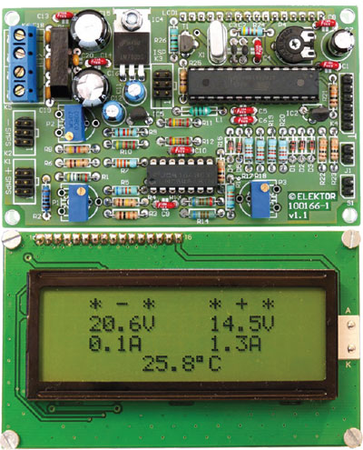
Dual Voltage/Current Display
For a symmetrical Unilab power supply

This is a MEMBER ONLY article. You need a subscription to read this article.
- Unlimited access to online Member Only articles
- 3 new editions Elektor Magazine (digital)
- More than 5000 Gerber files
- 20% member discount on e-books (at elektor.com)
- 10% member discount on Products (at elektor.com)
Available from €5.33 per month.
What is Members Only
Elektor is committed to providing high-quality content on electronics, catering to tens of thousands of paying members. As part of this commitment, Elektor has launched Premium, an initiative that offers exclusive online articles to members sometimes even before they appear in the magazine.
Every day, members can access in-depth articles that showcase the best of Elektor's premium content.
This initiative aims to reward members with early access. Once logged in, members can easily enjoy this exclusive content and engage in discussions about featured projects. While Premium adds to the existing resources available, Elektor will continue to provide a wealth of free information.
Join the Elektor community today to take advantage of Premium and other benefits!
Materials
Gerber file
CAM/CAD data for the PCB referred to in this article is available as a Gerber file. Elektor GREEN and GOLD members can exclusively download these files for free as part of their membership. Gerber files allow a PCB to be produced on an appropriate device available locally, or through an online PCB manufacturing service.
Elektor recommends the Elektor PCB Service service from its business partner Eurocircuits or AISLER as the best services for its own prototypes and volume production.
The use of our Gerber files is provided under a modified Creative Commons license. Creative Commons offers authors, scientists, educators and other creatives the freedom to handle their copyright in a more free way without losing their ownership.
Extra info / Update
Features
* Readings shown on a large backlit LCD module with 4 lines of 20 characters
* Voltage and current of each supply output (positive and negative) displayed
* Internal temperature of PS enclosure also displayed
* Selectable °C or °F temperature indication
* Signal conditioning circuitry specifically designed for a dual Unilab power supply
* Software-aided calibration procedure
* Powered by a separate transformer (2 ( 8 V / 3.3 VA)
Components
The BOM (Bill of Materials) is the technically exhaustive listing of parts and other hardware items used to produce the working and tested prototype of any Elektor Labs project. The BOM file contains deeper information than the Component List published for the same project in Elektor Magazine. If required the BOM gets updated directly by our lab engineers. As a reader, you can download the list here.
Want to learn more about our BOM list? Read the BOM list article for extra information.
Component list
(0.25 W unless indicated otherwise)
R1 = 499Ohm 1% 0.6W
R2 = 1.00kOhm 1% 0.6W
R3,R15,R21,R22,R23 = 10kOhm 5%
R4,R6 = 100kOhm 5%
R5,R16 = 68kOhm 5%
R7 = 3.3kOhm, 5%
R8 = 47kOhm 5%
R9 = 12kOhm 5%
R10 = 45.3kOhm 1% 0.6W
R11,R12 = 24.0kOhm 1% 0.5W
R13,R14 = 6.81kOhm 1% 0.6W
R17,R18,R19,R20 = 100Ohm 5%
R24 = 4.7Ohm 5%
R25 = 470Ohm 5%
R26 = 15Ohm 5 %
P1 = 200Ohm trimpot, e.g. Vishay Spectrol type M64W201KB40
P2 = 5kOhm trimpot, e.g. Vishay Spectrol type M64W502KB40
P3 = 500Ohm trimpot, e.g. Vishay Spectrol type M64W501KB40
P4 = 10kOhm trimpot, e.g. Piher type PT10LV10-103A2020
Capacitors
C1,C4,C5,C6,C8,C9,C10,C13,C14 = 100nF ceramic, lead pitch 5mm
C2,C3 = 15pF 2%, ceramic, lead pitch 5mm
C7 = 100µF 25V, radial, lead pitch 2.5mm
C11,C12 = 10µF 63V, radial, lead pitch 2.5mm
C15,C16 = 220µF 25V, radial, lead pitch 3.5 mm
C17,C18,C19,C20 = 47nF, ceramic, lead pitch 5mm
Inductor
L1 = 10µH 10%, axial, Rs = 0.29Ohm, e.g. Epcos type B78108S1103K
Halfgeleiders:
D1,D2,D3,D4,D5 = BAT85
T1 = BC639
IC1 = LMC6464BIN
IC2 = LM35CZ
IC3 = ATmega168-20PU, programmed, contained in kit # 100166-71
IC4 = 7805
IC5 = 79L05
B1 = 80V, 1.5A bridge rectifier (pinout ~ + ~ –), e.g. Semikron SKBB80C1500L5B
Miscellaneous
K1,K2,K3 = 6-pin (2x3) pinheader, lead pitch 0.1 in. (2.54mm)
K4 = 6-pin pinheader, lead pitch 0.1 in. (2.54mm)
K5,K6 = 2-way PCB terminal block, lead pitch 5mm
J1,S1 = 2-pin pinheader, lead pitch 0.1 in. (2.54mm)
LCD1 = 16-pin pinheader, lead pitch 0.1 in. (2.54mm)
LCD1 = 16-pin SIL connector for display, lead pitch 0.1 in. (2.54mm)
X1 = 10MHz quartz crystal, HC-49/S, 50ppm, CL = 12pF
LCD, 4x20 characters with background lighting, dim. 60 x 98 mm, e.g. HTDISPLAY HC200401C-YF62L-VA
PCB # 100166-1
Software en PCB design files: free download
Kit of parts incl. PCB, programmed controller and LCD: Elektor order # 100166-71


Discussion (0 comments)