SatFinder
TV dish alignment using GPS

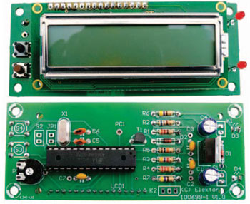
Those of you who regularly need to realign a satellite TV dish will find this gadget extremely valuable. Caravan owners and campers on long journeys who crave their home TV channels can now keep up with developments in sports, news and the soaps back home with the help of the SatFinder. This GPS based design includes a database containing positional information of a number of popular TV satellites. With the help of GPS data it calculates the precise angles to find the satellite first time!
This is a MEMBER ONLY article. You need a subscription to read this article.
- Access to Elektor archive and 5,000+ Gerber files
- Receive up to 8 magazines per year (digital and/or paper)
- 10% discount in the Elektor store
Available from €4.95 per month.
What is Members Only
Elektor is committed to providing high-quality content on electronics, catering to tens of thousands of paying members. As part of this commitment, Elektor has launched Premium, an initiative that offers exclusive online articles to members sometimes even before they appear in the magazine.
Every day, members can access in-depth articles that showcase the best of Elektor's premium content.
This initiative aims to reward members with early access. Once logged in, members can easily enjoy this exclusive content and engage in discussions about featured projects. While Premium adds to the existing resources available, Elektor will continue to provide a wealth of free information.
Join the Elektor community today to take advantage of Premium and other benefits!
Materials
Gerber file
CAM/CAD data for the PCB referred to in this article is available as a Gerber file. Elektor GREEN and GOLD members can exclusively download these files for free as part of their membership. Gerber files allow a PCB to be produced on an appropriate device available locally, or through an online PCB manufacturing service.
Elektor recommends the Elektor PCB Service service from its business partner Eurocircuits or AISLER as the best services for its own prototypes and volume production.
The use of our Gerber files is provided under a modified Creative Commons license. Creative Commons offers authors, scientists, educators and other creatives the freedom to handle their copyright in a more free way without losing their ownership.
Extra info / Update
* TV dish azimuth and elevation angle display calculated from GPS data for 33 preinstalled TV satellites
* Display of GPS positioning data (geographical latitude and longitude)
* NMEA (RMC) input
* Input signal data rate switchable between 4800 and 9600 bps
* Input signal level switchable between RS232 and TTL
* Programming language: BASCOM-AVR
* All stored satellite data can be reprogrammed
* Source and hexcode files both free to download
* ISP interface for microcontroller programming
* Test pin for serial data output (TTL level, data rate same as serial input data)
* Operates from 12 V supply (external power from 8 to 15 V)
* Supplies 3.3 V or 5 V to the GPS module
* Supply current (no GPS module connected and without LCD backlight) approx 30 mA at 12 V
Components
The BOM (Bill of Materials) is the technically exhaustive listing of parts and other hardware items used to produce the working and tested prototype of any Elektor Labs project. The BOM file contains deeper information than the Component List published for the same project in Elektor Magazine. If required the BOM gets updated directly by our lab engineers. As a reader, you can download the list here.
Want to learn more about our BOM list? Read the BOM list article for extra information.
Component list
R1 = 220Ohm
R2 = 680Ohm
R3 = 4.7kOhm
R4 = 22kOhm
R5 = 10kOhm
R6,R7 = 470Ohm
R8 = 68Ohm
P1 = 10kOhm trimpot (horizontal)
Capacitors
C1,C4 = 100µF 25V radial
C2,C3,C7 = 100nF
C5,C6 = 22pF
C8 = 10µF 25V radial
Semiconductors
D1,D2 = 1N4148
D3,D4 = LED, 3mm, low current
T1 = BC547B
IC1 = LM317T
IC2 = ATMEGA8A-PU, programmed, Elektor # 100699-41
IC3 = LM2950 3V3
Miscellaneous
JP1 = 2-pin pinheader, lead pitch 0.1 in. (2.54mm), with jumper
K1 = 2-pin pinheader, lead pitch 0.1 in. (2.54mm)
K2 = 3-pin pinheader, lead pitch 0.1 in. (2.54mm)
K3 = 6-pin (2x3) pinheader, lead pitch 0.1 in. (2.54mm)
S1,S2 = single pole switch
S3,S4 = pushbutton, 1 make contact, e.g. Multicomp # MC32830
X1 = 8MHz quartz crystal, e.g. Vishay Dale type XT49S-208M
LCD1 = 2x16 characters, e.g. Lumex S01602 D/A
PCB # 100699-1


Discussion (0 comments)