

Wave Sound Generator
Restful electronics
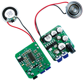
It doesn’t take a lot of electronics to produce simulated wave sounds. A variety of circuits for this have been published in past issues of Elektor magazine. In light of recent growing interest in a design for a wave sound generator, we took a close look at the previous version (published in February 1996) and transformed it into an updated and very compact design.
This is a MEMBER ONLY article. You need a subscription to read this article.
- Unlimited access to online Member Only articles
- 3 new editions Elektor Magazine (digital)
- More than 5000 Gerber files
- 20% member discount on e-books (at elektor.com)
- 10% member discount on Products (at elektor.com)
Available from €5.33 per month.
What is Members Only
Elektor is committed to providing high-quality content on electronics, catering to tens of thousands of paying members. As part of this commitment, Elektor has launched Premium, an initiative that offers exclusive online articles to members sometimes even before they appear in the magazine.
Every day, members can access in-depth articles that showcase the best of Elektor's premium content.
This initiative aims to reward members with early access. Once logged in, members can easily enjoy this exclusive content and engage in discussions about featured projects. While Premium adds to the existing resources available, Elektor will continue to provide a wealth of free information.
Join the Elektor community today to take advantage of Premium and other benefits!
Materials
Gerber file
CAM/CAD data for the PCB referred to in this article is available as a Gerber file. Elektor GREEN and GOLD members can exclusively download these files for free as part of their membership. Gerber files allow a PCB to be produced on an appropriate device available locally, or through an online PCB manufacturing service.
Elektor recommends the Elektor PCB Service service from its business partner Eurocircuits or AISLER as the best services for its own prototypes and volume production.
The use of our Gerber files is provided under a modified Creative Commons license. Creative Commons offers authors, scientists, educators and other creatives the freedom to handle their copyright in a more free way without losing their ownership.
Component list
R1,R3,R4–R7,R9,R11,R13,R14,R18,R24 = 100kOhm (0805)
R2 = 33kOhm (0805)
R8 = 220kOhm (0805)
R10 = 470kOhm (0805)
R12 = 150kOhm (0805)
R15,R17 = 1MOhm (0805)
R16,R19,R21 = 1kOhm (0805)
R22,R23 = 47kOhm (0805)
P1 = 100kOhm trimpot (3306W)
P2 = 50kOhm trimpot (3306W)
Capacitors (SMD)
C1 = 100nF (0805)
C2,C3 = 100µF 16V (case-d)
C4 = 47µF 16V (case-d)
C5,C9 = 10µF 16V (case-b)
C6,C11 = 220µF 16V (case-e)
C7,C10 = 47nF (0805)
C8 = 220pF
Semiconductors (SMD)
D1 = BAT42W
T1,T2 = BC847
T4 = BCP53
T3 = BCP56
IC3 = LM2937IMP-12/NOPB
IC2 = TL084ACD
Miscellaneous
K1 = power adaptor socket (CUI PJ-007)
LS1 = miniature loudspeaker, e.g. Kingstate KDMG20008, Farnell # 1502730)
PCB # 100922-1
Assembled board # 100922-91
Discussion (0 comments)