

Here comes the Bus! (6)
Part 6: Elektor experimental PCBs and more
Gerber file
CAM/CAD data for the PCB referred to in this article is available as a Gerber file. Elektor GREEN and GOLD members can exclusively download these files for free as part of their membership. Gerber files allow a PCB to be produced on an appropriate device available locally, or through an online PCB manufacturing service.
Elektor recommends the Elektor PCB Service service from its business partner Eurocircuits or AISLER as the best services for its own prototypes and volume production.
The use of our Gerber files is provided under a modified Creative Commons license. Creative Commons offers authors, scientists, educators and other creatives the freedom to handle their copyright in a more free way without losing their ownership.
Components
The BOM (Bill of Materials) is the technically exhaustive listing of parts and other hardware items used to produce the working and tested prototype of any Elektor Labs project. The BOM file contains deeper information than the Component List published for the same project in Elektor Magazine. If required the BOM gets updated directly by our lab engineers. As a reader, you can download the list here.
Want to learn more about our BOM list? Read the BOM list article for extra information.
Component list
Experimental Node
Resistors
R1,R8 = 680Ohm
R2,R3,R6 = 10kOhm
R4 = 120Ohm
R7 = 2.2kOhm
R9,R10 = 4.7kOhm
Capacitors
C1,C2 = 22pF
C3,C4,C8 = 4.7µF
C5,C6,C7 = 100nF
Semiconductors
D1 = 1N4004
IC1 = ATmega88-20PU
IC2 = LT1785
IC3 = 78L05
Miscellaneous
X1 = 16MHz quartz crystal
S1,S2,S3 = pushbutton
JP1,JP2= jumper
LED1 = LED, 3mm, red
LED2 = LED, 3mm, green
LED3 = LED, 3mm, yellow
K1 = 6-pin (2x3) pin header, lead pitch 2.54mm (0.1 in.)
K4 = 8-pin pin header, lead pitch 2.54mm (0.1 in.)
K2,K3 = 4-way PCB screw terminal block, lead pitch 5.08mm (0.2 in.)
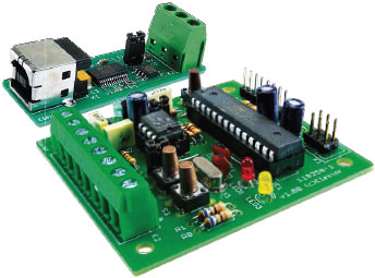
PCB # 110258-1
USB/RS485 Converter
Resistors
R1 = 10kOhm (0805)
R2 = 120Ohm (0805)
Capacitors
C1,C2 = 100nF
C3 = 10µF 16V (6032)
Semiconductors
IC1 = FT232RL
IC2 = LT1785 (SO-8)
Miscellaneous
JP1 = jumper
K1 = USB socket Type A
K2 = 3-way PCB screw terminal block, lead pitch 5.08mm (0.2 in.)
PCB # 110258-2
or
ready assembled and tested PCB # 110258-91
We buy at:

Discussion (0 comments)