Article
AndroPod (1)
Part 1: A serial interface for Android smartphones and tablets
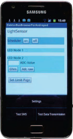
With their high-resolution touchscreens, ample computing power, WLAN support and telephone functions, Android smartphones and tablets are ideal for use as control centres in your own projects. However, up to now it has been rather difficult to connect them to external circuitry. Our AndroPod interface board, which adds a serial TTL port and an RS485 port to the picture, changes this situation.
Materials
Component list
Resistors (1%, 0603)
R1–R4 = 27Ohm
R5,R6 = 180Ohm
R7–R13,R16 = 10kOhm
R14 = 6.04kOhm
R15 = 1kOhm
R17 = 120Ohm
R18,R19 = 680Ohm (recommended value)
Capacitors
C1,C2,C6–C12,C21 = 100nF 50V (10%, X7R, ceramic multi-layer 0603)
C3,C4,C5,C13 = 47µF 10V (20%, ESR 0.7, tantalum, case B 1210)
C14,C15 = 18pF 50V (5%, C0G/NP0, ceramic multi-layer 0603)
C16 = 10µF 16V (10 %, tantalum, case B 1210)
C17 = 1µF 25V (10 %, X7R, ceramic multi-layer 0805)
C18 = 220nF / 25V (10%, X7R, ceramic multi-layer 0603)
C19,C20 = 4.7µF 10V (10%, X5R, ceramic multi-layer 0805)
Cx = not fitted
Inductors
L1-L6 = ferrite bead, 600Ohm @ 100MHz, 500mA (0603)
L7 = 18µH choke (1.25A)
Semiconductors
D1 = zener diode 5.6V 3W
D2 = zener diode 3.6V 375mW
D3 = green LED (0603)
D4 = yellow LED (0603)
D5–D8 = bipolar suppressor diode (0603)
D9,D12 = ES1G diode fast recovery 1A 400V
D10,D11 = B130-13-F Schottky diode 1A 30V
IC1 = 3.3V voltage LDO regulator 1.3A (SOT-223)
IC2 = MIC2005 0.5 A current limiting power distribution switch (SOT-23-6L)
IC3 = Vinculum II USB Host Controller (QFN32)
IC4 = LM2842 600 mA step-down DC/DC regulator (TSOT-6)
IC5 = LT1785 RS485-Transceiver (SOIC8)
Miscellaneous
X1 = 12MHz quartz crystal (18pF 30ppm)
F1 = 750mA Polyfuse
S1 = 4-pin (2x2) pinheader with jumper, or 2-way DIP switch
K1 = USB Micro-B socket
K2 = USB A socket
K3 = 6-pin pinheader (2.0mm)
K4 = 6-pin pinheader (0.1’’)
K5,K6 = 8-pin pinheader (0.1’’)
K7 = 2.0mm power adapter plug
K8 = 4-way PCB screw terminal block (5.00mm)
K9 = 8-way mini DIN socket
JP1 = 3-pin pinheader (0.1’’) + 1 pin + jumper
JP2 = 2-pin pinheader (0.1’’) with jumper
JP3 = solder bridge
JP4 = 3-pin pinheader (0.1’’) with jumper
Discussion (0 comments)