Pico C-Plus and Pico C-Super
Elektor’s ‘small-C’ meter upgraded in two ways

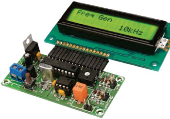
The popularity of All Things Test & Measurement among Elektor readers got substantiated once again recently by Pico C, a cute DIY capacitance meter specially designed to deal with small capacitors like below 10 pF, much to the enjoyment of radio amateurs and leaving professional instruments well behind. One limitation of the instrument was noted though, its maximum value of about 2500 pF, triggering reader Jon Drury to write new software culminating in two new versions called Pico C-Plus and Pico C-Super. C+? No, assembly language was used to write the firmware.
This is a MEMBER ONLY article. You need a subscription to read this article.
- Access to Elektor archive and 5,000+ Gerber files
- Receive up to 8 magazines per year (digital and/or paper)
- 10% discount in the Elektor store
Available from €4.95 per month.
What is Members Only
Elektor is committed to providing high-quality content on electronics, catering to tens of thousands of paying members. As part of this commitment, Elektor has launched Premium, an initiative that offers exclusive online articles to members sometimes even before they appear in the magazine.
Every day, members can access in-depth articles that showcase the best of Elektor's premium content.
This initiative aims to reward members with early access. Once logged in, members can easily enjoy this exclusive content and engage in discussions about featured projects. While Premium adds to the existing resources available, Elektor will continue to provide a wealth of free information.
Join the Elektor community today to take advantage of Premium and other benefits!
Materials
Gerber file
CAM/CAD data for the PCB referred to in this article is available as a Gerber file. Elektor GREEN and GOLD members can exclusively download these files for free as part of their membership. Gerber files allow a PCB to be produced on an appropriate device available locally, or through an online PCB manufacturing service.
Elektor recommends the Elektor PCB Service service from its business partner Eurocircuits or AISLER as the best services for its own prototypes and volume production.
The use of our Gerber files is provided under a modified Creative Commons license. Creative Commons offers authors, scientists, educators and other creatives the freedom to handle their copyright in a more free way without losing their ownership.
Extra info / Update
Extended capacitance range: <1 pF to 500 nF, max. resolution 0.01 pF
3 capacitance ranges: 5 nF, 50 nF, 500 nF
Pico C-Plus: software upgrade only; no PCB modifications required
Pico C-Super: software upgrade & minor PCB alterations required. Reworked PCB available.
Period meter ranges: 16 ms, 160 ms, 1.6 s
Frequency meter range: 8 MHz, max resolution 1 Hz
Signal Generator:
- range 0.8 Hz – 10 MHz
- resolution 0.1% up to 10 kHz, 1% across 10 kHz – 100 kHz
- square wave 0 – 5 V
Components
The BOM (Bill of Materials) is the technically exhaustive listing of parts and other hardware items used to produce the working and tested prototype of any Elektor Labs project. The BOM file contains deeper information than the Component List published for the same project in Elektor Magazine. If required the BOM gets updated directly by our lab engineers. As a reader, you can download the list here.
Want to learn more about our BOM list? Read the BOM list article for extra information.
Component list
Resistors
R1 = 1MOhm 1%
R2 = 5.6Ohm 5%
R3,R4 = 100Ohm 5%
P1 = 10kOhm 20%, preset
Capacitors
C1 = 10?F, 63V, lead spacing 2.5mm
C2,C3,C4 = 100nF 50V ceramic, lead spacing 0.2’’ (5.08mm)
C5,C6 = 15pF 100V 5%, ceramic, lead spacing 0.2’’ (5.08mm)
C7 = 220pF 63V 1%, polystyrene, lead spacing 7.18mm
Semiconductors
D1 = 1N4004
D2-D5 = BAT85
IC1= 7805
IC2= TLC555
IC3 = ATtiny2313, programmed, Elektor # 110687-42*
Miscellaneous
JP1,K2,K3,K4 = 2-pin pinheader, straight, lead pitch 0.1’’ (2.54mm)
JP1 =jumper 0.1’’ (2.54mm)
K1 = 2-way PCB screw terminal block, lead pitch 5mm
K2,K3,K4 = 2-way socket, straight, lead pitch 0.1’’ (2.54mm)
LCD1 = LCD, 2x16 (TC1602C-01YA0_A00), Elektor # 120061-71*. Check pinout when using any other device.
LCD1 socket = 16-way SIL, lead spacing 0.1’’ (2.54mm), right angled
LCD1 plug = 16-pin pinheader, lead spacing 0.1’’ (2.54mm), right angled
S1 = pushbutton, SPNO, tactile feedback, 6mm
X1 = 20MHz quartz crystal, CL = 18pF, 50ppm
PCB # 110687-1


Discussion (0 comments)