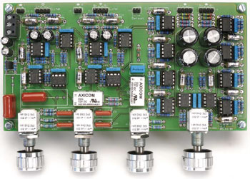
Preamplifier 2012 (1)
Part 1: introduction and line-in/tone/volume board

This is a MEMBER ONLY article. You need a subscription to read this article.
- Unlimited access to online Member Only articles
- 3 new editions Elektor Magazine (digital)
- More than 5000 Gerber files
- 20% member discount on e-books (at elektor.com)
- 10% member discount on Products (at elektor.com)
Available from €5.33 per month.
What is Members Only
Elektor is committed to providing high-quality content on electronics, catering to tens of thousands of paying members. As part of this commitment, Elektor has launched Premium, an initiative that offers exclusive online articles to members sometimes even before they appear in the magazine.
Every day, members can access in-depth articles that showcase the best of Elektor's premium content.
This initiative aims to reward members with early access. Once logged in, members can easily enjoy this exclusive content and engage in discussions about featured projects. While Premium adds to the existing resources available, Elektor will continue to provide a wealth of free information.
Join the Elektor community today to take advantage of Premium and other benefits!
Materials
Gerber file
CAM/CAD data for the PCB referred to in this article is available as a Gerber file. Elektor GREEN and GOLD members can exclusively download these files for free as part of their membership. Gerber files allow a PCB to be produced on an appropriate device available locally, or through an online PCB manufacturing service.
Elektor recommends the Elektor PCB Service service from its business partner Eurocircuits or AISLER as the best services for its own prototypes and volume production.
The use of our Gerber files is provided under a modified Creative Commons license. Creative Commons offers authors, scientists, educators and other creatives the freedom to handle their copyright in a more free way without losing their ownership.
Extra info / Update
Specifications
Test conditions: supply voltage ±17.6 V; all measurements symmetrical; tone control defeat disabled.
Test equipment: Audio Precision Two Cascade Plus 2722 Dual Domain (@Elektor Labs)
THD+N (200 mV in, 1 V out) 0.0015% (1 kHz, B = 22 Hz – 22 kHz)
0.0028% (20 kHz, B = 22 Hz – 80 kHz)
THD+N (2 V in, 1 V out) 0.0003% (1 kHz, B = 22 Hz – 22 kHz)
0.0009% (20 kHz, B = 22 Hz – 80 kHz)
S/N (200 mV in) 96 dB (B = 22 Hz – 22 kHz)
98.7 dBA
Bandwidth 0.2 Hz – 300 kHz
Max. output voltage (200 mV in) 1.3 V
Balance +3.6 dB to –6.3 dB
Tone control ±8 dB (100 Hz)
±8.5 dB (10 kHz)
Crosstalk R to L –98 dB (1 kHz)
–74 dB (20 kHz)
L to R –102 dB (1 kHz)
–80 dB (20 kHz)
Component list
(1% tolerance; metal film; 0.25W)
R1,R2,R39,R40 = 100Ohm
R3-R6,R41-R44,R78,R79 = 100kOhm
R7-R12,R16,R17,R21-R24,R33,R34,
R45-R50,R54,R55,R59-R62,R71,R72 = 1kOhm
R13,R51 = 470Ohm
R14,R15,R52,R53 = 430Ohm
R18,R35,R36,R56,R73,R74 = 22kOhm
R19,R20,R57,R58 = 20Ohm
R25-R28,R63-R66 = 3.3kOhm
R29-R32,R67-R70 = 10Ohm
R37,R38,R75,R76 = 47Ohm
R77 = 120Ohm
P1,P2,P3,P4 = 1kOhm, 10%, 1W, stereo potentiometer, linear law, e.g. Vishay Spectrol cermet type 14920F0GJSX13102KA. Alternatively, Vishay Spectrol conductive plastic type 148DXG56S102SP (RS Components p/n 484-9146).
Capacitors
C1,C2,C10-C14,C26,C27,C35-C39 = 100pF 630V, 1%, polystyrene, axial
C3,C4,C28,C29 = 47µF 35V, 20%, bipolar, diam. 8mm, lead spacing 3.5mm, e.g. Multicomp p/n NP35V476M8X11.5
C5,C6,C30,C31 = 470pF 630V, 1%, polystyrene, axial
C7,C32 = 1µF 250V, 5%, polypropylene, lead spacing 15mm
C8,C9,C33,C34 = 100nF 250V, 5%, polypropylene, lead spacing 10mm
C15,C16,C40,C41 = 220µF 35V, 20%, bipolar, diam. 13mm, lead spacing 5mm, e.g. Multicomp p/n NP35V227M13X20
C17-C25,C42-C50 = 100nF 100V, 10%, lead spacing 7.5mm
C51 = 470nF 100V, 10%, lead spacing 7.5mm
C52,C53 = 100µF 25V, 20%, diam. 6.3mm, lead spacing 2.5mm
Semiconductors
IC1,IC3,IC5-IC10,IC12,IC14-IC18 = NE5532, e.g. ON Semiconductor type NE5532ANG
IC2,IC4,IC11,IC13 = LM4562, e.g. National Semiconductor type LM4562NA/NOPB
Miscellaneous
K1-K4 = 4-pin straight pinheader, pitch 0.1’’ (2.54mm), with mating sockets
K5,K6,K7 = 2-pin pinheader, pitch 0.1’’ (2.54mm), with mating sockets
JP1 = 2-pin pinheader, pitch 0.1’’ (2.54mm), with jumper
K8 = 3-way PCB screw terminal block, pitch 5mm
RE1,RE2 = relay, 12V/960Ohm, 230VAC/3A, DPDT, TE Connectivity/Axicom type V23105-A5003-A201
PCB # 110650-1
Note: all parts available from Farnell (but not exclusively), except PCB 110650-1.


Discussion (0 comments)
Malcolm Mr Bloor 8 years ago
C Gunn 5 years ago
The treble does not change when adjusting the pot
Measured the AC voltage on both outputs no change . Placed it on the scope and have seen no change in amplitide when adjusting the treble as compared to the bass.
Any comments on this would be appreciated
Have Denon Bluetooth to XLR input , DAC to RCA and Turntable to MM input . All working
Complete the enclosure in black walnut with a stainless steel front plate . The connection finished off with carbon fiber . Did the design with solidworks software and had the wood and metal cut out with a CNC machine
EN0179739ID 3 years ago
i want preamp for my personal use ,can you send me this product.