Article
Universal Measurement Amplifier / Attenuator
For laptop or PC

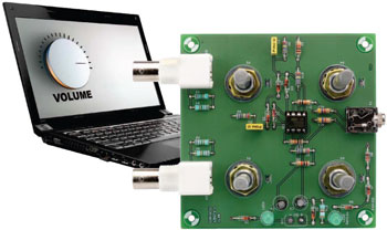
A computer is suitable for making (audio) measurements thanks to the sound card that is usually built in. Unfortunately, the audio input on laptops is usually too sensitive to measure somewhat larger AC voltages. A small amplifier/attenuator circuit then comes in very handy. If you build or repair audio equipment yourself, you don’t always need an oscilloscope.
Materials
Gerber file
CAM/CAD data for the PCB referred to in this article is available as a Gerber file. Elektor GREEN and GOLD members can exclusively download these files for free as part of their membership. Gerber files allow a PCB to be produced on an appropriate device available locally, or through an online PCB manufacturing service.
Elektor recommends the Elektor PCB Service service from its business partner Eurocircuits or AISLER as the best services for its own prototypes and volume production.
The use of our Gerber files is provided under a modified Creative Commons license. Creative Commons offers authors, scientists, educators and other creatives the freedom to handle their copyright in a more free way without losing their ownership.
PCB
Extra info / Update
Note: Since the original publication of this project/article, some of the components, software elements, webpages and other elements might have been updated or changed.
Component list
Resistors
R1–R4 = 1.8MOhm
R5,R9 = 1kOhm
R6,R7,R8,R10 = 1MOhm
R11,R13 = 10kOhm
R12,R14 = 4.7kOhm
R15 = 3.9kOhm
P1,P2 = 100kOhm potentiometer, logarithmic law
P3,P4 = 100kOhm potentiometer, linear law
Capacitors
C1,C2 = 100nF MKT, pitch 5mm
C3,C4 = 10µF 16V, 6mm diam., pitch 2.5mm
Semiconductors
D1–D9 = BAT48 (DO-35 case)
IC1 = TS922IN (dual opamp, DIP-8 case)
LED1,LED2 = LED, green, 5mm
Miscellaneous
K1 = 3.5mm stereo socket (e.g. Lumberg 1503-09)
K2,K3 = BNC connector, right angled pins, PCB mount (e.g. TE connectivity 1-1337543-0)
BT1 = 9V battery clip
PCB # 120272-1


Discussion (0 comments)