

Shoo Heron!
Outsmart a clever bird
The idea is to protect the pond with an invisible barrier that is connected to a powerful water spray. Herons dislike being sprayed and will leave. Furthermore, they can’t easily determine what causes the spray to start.
The protection consists of an infrared transmitter and receiver that are mounted close to each other.
This is a MEMBER ONLY article. You need a subscription to read this article.
- Access to Elektor archive and 5,000+ Gerber files
- Receive up to 8 magazines per year (digital and/or paper)
- 10% discount in the Elektor store
Available from €4.95 per month.
What is Members Only
Elektor is committed to providing high-quality content on electronics, catering to tens of thousands of paying members. As part of this commitment, Elektor has launched Premium, an initiative that offers exclusive online articles to members sometimes even before they appear in the magazine.
Every day, members can access in-depth articles that showcase the best of Elektor's premium content.
This initiative aims to reward members with early access. Once logged in, members can easily enjoy this exclusive content and engage in discussions about featured projects. While Premium adds to the existing resources available, Elektor will continue to provide a wealth of free information.
Join the Elektor community today to take advantage of Premium and other benefits!
Materials
Gerber file
CAM/CAD data for the PCB referred to in this article is available as a Gerber file. Elektor GREEN and GOLD members can exclusively download these files for free as part of their membership. Gerber files allow a PCB to be produced on an appropriate device available locally, or through an online PCB manufacturing service.
Elektor recommends the Elektor PCB Service service from its business partner Eurocircuits or AISLER as the best services for its own prototypes and volume production.
The use of our Gerber files is provided under a modified Creative Commons license. Creative Commons offers authors, scientists, educators and other creatives the freedom to handle their copyright in a more free way without losing their ownership.
Component list
R1,R2 = 10kOhm
R3 = 1kOhm
Capacitors
C1 = 10µF 63V radial, pitch 2mm
C2,C5,C7 = 100nF, pitch 7.5mm
C3,C4 = 1µF 63V radal, pitch 2mm
C6 = 220µF 35V radial, pitch 3.5 or 5mm
C8–C11 = 10nF, pitch 5mm
Halfgeleiders:
D1–D4 = 1N4004
IC1 = PIC12F509-I/P, programmed
IC2 = S202T02F
IC3 = 7805
IC4 = 7812
Miscellaneous
F1 = fuse, 250mAT, w. PCB mount holder and cap
K1,K2 = 2-way PCB terminal block, pitch 7.5mm
K3 = 2-way PCB terminal block, pitch 5mm
K4 = 3-way PCB terminal block, pitch 5mm
TR1 = power transformer, secondary 2x6V, 1.5VA (e.g. Block AVB1,5/2/6)
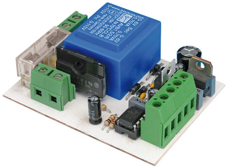
PCB # 110337-1
Discussion (0 comments)