USB Isolator
Avoid interference and earth loops

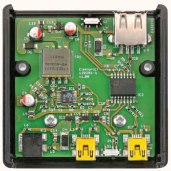
If your USB device ever suffers from noise caused by an earth loop or if you want to protect your PC against external voltages then you need a USB isolator. The circuit described here offers an optimal electrical isolation of both the data lines as well as the supply lines between the PC and the USB device.The project itself is a spin-off from an earlier design for a portable oscilloscope for Android.
Materials
Gerber file
CAM/CAD data for the PCB referred to in this article is available as a Gerber file. Elektor GREEN and GOLD members can exclusively download these files for free as part of their membership. Gerber files allow a PCB to be produced on an appropriate device available locally, or through an online PCB manufacturing service.
Elektor recommends the Elektor PCB Service service from its business partner Eurocircuits or AISLER as the best services for its own prototypes and volume production.
The use of our Gerber files is provided under a modified Creative Commons license. Creative Commons offers authors, scientists, educators and other creatives the freedom to handle their copyright in a more free way without losing their ownership.
Extra info / Update
• Electrically isolated data and power supply lines
• Configurable data rate of 1.5 Mbit/s or 12 Mbit/s
• Power for the device side can be taken from an extra USB host connection or an external AC power adapter (5 V/min. 0.5 A)
• Transformer isolation = 1500 VAC for 1 min
• ADuM3160 isolation = 565 Vpeak for 50 years
• Maximum output current Iout = 500 mA @ 5 V
Component list
Resistors
(1% 0.1W, SMD 0603, unless otherwise shown)
R1 = 1kOhm 1% 0.5W (SMD 1206)
R2 = 33kOhm
R3 = 80.6kOhm
R4 = 6.04kOhm
R5 = 200kOhm
R6 = 90.9kOhm
R7,R8 = 28.7kOhm
R9,R10,R11,R12 = 24Ohm
R13,R14 = 4.7kOhm
Capacitors
C1,C2 = 10nF 16V X7R (SMD 0603)
C3 = 220nF 50V X5R (SMD 0603)
C4,C5,C6 = 120µF 6.3V (Nichicon RFS0J121MCN1GS, type C)
C7,C8,C9,C10,C11,C12 = 100nF 25V X7R (SMD 0603)
C13,C14,C15,C16 = 10µF 6.3V X5R (SMD 0805)
Inductors
L1,L2,L3,L4,L5,L6,L7,L8 = ferrite inductor 33Ohm@100MHz (SMD 0603) e.g. Murata BLM18PG330SN1D
L9,L10 = 1µH 1.2A (SMD 1007) e.g. Taiyo Yuden CB2518T1R0M
Semiconductors
D1 = PMEG3050BEP (NXP) (SOD-128)
D2 = PMEG6010CEH (NXP) (SOD-123f)
D3,D4 = 5.6V 3W zener diode
IC1 = LT3575EFE#PBF (LT) (TTSOP-16)
IC2 = ADUM3160BRWZ (AD) (SOICW-16)
IC3 = NCP380HSN10AAT1G (On Semiconductor) (TSOP-5)
IC4,IC5,IC6 = NCP380HSN05AAT1G (On Semiconductor) (TSOP-5)
IC7,IC8 = TPD2EUSB30ADRTR (TI) (SOT-3)
Miscellaneous
S1,S2 = slide switch with changeover contact (e.g. C&K Components PCM12SMTR)
K1,K2 = USB mini-B-connector, PCB mount (e.g. On-Shore USB-M26FTR)
K3 = DC adapter connector, 1.35 mm (e.g. CUI PJ-014DH-SMT)
K4 = USB-A connector, PCB mount (e.g. FCI 87583-2010BLF)
TR1 = transformer 3:1, 25 µH (e.g. Würth 750310471)
Case, Hammond type 1593KBK
2 self tapping screws, cross head, 4x6.4mm, DIN7981
PCB # 120291-1 or
assembled and tested board and case, # 120291-91


Discussion (0 comments)