Article
Intelligent PC Fan Controller
Controls a maximum of 6 PWM fans
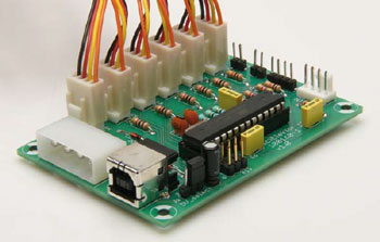
In a modern PC you will find a number of fans for removing the heat that is generated. These can’t always be controlled individually by the PC motherboard. With the help of the circuit described here you can actively control up to six fans, while the temperature can be measured in various places inside the PC case using a number of sensors. A PC program is used to configure and monitor the fans, which communicates with the fan control board via a USB link.
Materials
Gerber file
CAM/CAD data for the PCB referred to in this article is available as a Gerber file. Elektor GREEN and GOLD members can exclusively download these files for free as part of their membership. Gerber files allow a PCB to be produced on an appropriate device available locally, or through an online PCB manufacturing service.
Elektor recommends the Elektor PCB Service service from its business partner Eurocircuits or AISLER as the best services for its own prototypes and volume production.
The use of our Gerber files is provided under a modified Creative Commons license. Creative Commons offers authors, scientists, educators and other creatives the freedom to handle their copyright in a more free way without losing their ownership.
PCB
Extra info / Update
• Autonomous individual control of up to six 4-wire PWM fans.
• Measurement of the rotational speed of these fans and detection of stalled fans.
• Support for a maximum of 8 sensors to control the fan speed:
2 NTCs
I2C temperature sensors, MCP980x/TCN75 compatible
Rotational speed of fans can also be used as a ‘sensor’ signal
External ‘sensors’, where the value can be set via USB
The duty-cycle of an external fan control signal, such as emanating from a motherboard
• The rotational speed can be set in three ways:
Constant
Linear control where the rotational speed depends on a sensor signal
PI-controlled that uses a sensor signal and a required sensor value to calculate the rotational speed
• Configuration and monitoring via USB.
• Software library for use in PC applications to let you communicate with the circuit and a PC application to configure and drive the circuit, for Windows as well as Linux.
Component list
Resistors
R1,R2 = 68Ohm
R3 = 100kOhm
R4,R8,R9 = 10kOhm
R5 = 1.5kOhm
R6,R7 = 4.7kOhm
R10-R15 = 1kOhm
Capacitors
C1 = 10µF 16V radial, lead pitch 2.5mm
C2,C5,C6 = 100nF, lead pitch 5mm
C3,C4 = 22pF
Semiconductors
D1,D2 = 3.6V zener diode, 400mW
IC1 = ATmega168PA-PU, programmed, Elektor # 100160-41
Miscellaneous
X1 = 16MHz quartz crystal
J1 = 3-pin pinheader with jumper
K1-K6,K7 = 4-pin fan header
K8 = 4-pin PC supply plug, PCB mount
K9 = Mini USB-B connector, PCB mount
K10 = 4-pin pinheader
K11,K12 = 2-pin pinheader
K13 = 6-pin (2x3) boxheader
PCB # 100160-1
Discussion (0 comments)