Nixie VU Meter
A warm & retro power indicator for the tube amp
Materials
Gerber file
CAM/CAD data for the PCB referred to in this article is available as a Gerber file. Elektor GREEN and GOLD members can exclusively download these files for free as part of their membership. Gerber files allow a PCB to be produced on an appropriate device available locally, or through an online PCB manufacturing service.
Elektor recommends the Elektor PCB Service service from its business partner Eurocircuits or AISLER as the best services for its own prototypes and volume production.
The use of our Gerber files is provided under a modified Creative Commons license. Creative Commons offers authors, scientists, educators and other creatives the freedom to handle their copyright in a more free way without losing their ownership.
Extra info / Update
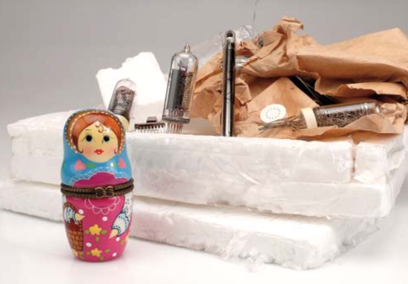
* 2 x IN-9 linear gas discharge (Nixie) tube
* Column colour: warm orange/pink
* Net column height: 85 mm (approx.)
* Audio ‘Line’ drive level (approx. 0.7 V)
* Cypress PSoC CY8C27443 based
* PSoC device available ready-programmed
* Software lin/log converter
* Onboard 150 VDC supply
* Compact board (65 x 65 mm)
Components
The BOM (Bill of Materials) is the technically exhaustive listing of parts and other hardware items used to produce the working and tested prototype of any Elektor Labs project. The BOM file contains deeper information than the Component List published for the same project in Elektor Magazine. If required the BOM gets updated directly by our lab engineers. As a reader, you can download the list here.
Want to learn more about our BOM list? Read the BOM list article for extra information.
Component list
Resistors
(all fixed Rs SMA shape 0805)
R1,R2,R5,R8 = 1kOhm
R3,R6 = 100kOhm
R4,R7 = 470Ohm
R9 = 2.2kOhm
R10 = 220kOhm
R11 = 10kOhm
R12 = 33kOhm
R13 = 47Ohm
P1,P2 = 220Ohm preset, top adjust
P23 = 1kOhm preset, top adjust
Capacitors
C1,C4 = 470nF (SMD 0805)
C2,C11,C17 = 10µF 16V radial, lead pitch 2.5mm
C3,C5,C6,C7,C8,C9,C10,C13,C14 = 100nF (SMD 0805)
C12 = 1µF 250V (SMD shape 1825)
C15 = 2.2nF (SMD shape 0805)
C16 = 470µF 25V radial, lead pitch 5mm
Inductors
L1 = 100µH, 860mA, Multicomp MCSDRH73B-101MHF
Semiconductors
D1,D2,D3,D4 = BAT46WH
D5 = 1N4001 BYV26
D6 = BZD27C5V1P 5.1V zener diode
T1,T2 = MMBTA42
T3 = IRF640NSPBF
T4 = BC847
IC1 = CY8C27443-24SXI, Elektor # 110744-41*
IC2 = MCP101-475HI/TO
IC3 = LM324ADT (SOIC-14)
IC4 = NE555DT (SOIC-8)
IC5,IC6 = 78L05
Miscellaneous
K1 = 3.5mm stereo jack, PCB mount (Lumberg 1503 09)
K2 = 5-pin SIL pinheader, 0.1’’ pitch (2.54mm)
K3 = 2-way PCB screw terminal block, 5mm pitch
V1,V2 = 2-way PCB screw terminal block, 5mm pitch
2 pcs IN-9 Nixie tube
PCB # 110744-1
Discussion (0 comments)