

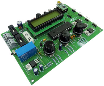
Ambience Lighting Controller
Setting the mood with RGB LEDs
This is a MEMBER ONLY article. You need a subscription to read this article.
- Unlimited access to online Member Only articles
- 3 new editions Elektor Magazine (digital)
- More than 5000 Gerber files
- 20% member discount on e-books (at elektor.com)
- 10% member discount on Products (at elektor.com)
Available from €5.33 per month.
What is Members Only
Elektor is committed to providing high-quality content on electronics, catering to tens of thousands of paying members. As part of this commitment, Elektor has launched Premium, an initiative that offers exclusive online articles to members sometimes even before they appear in the magazine.
Every day, members can access in-depth articles that showcase the best of Elektor's premium content.
This initiative aims to reward members with early access. Once logged in, members can easily enjoy this exclusive content and engage in discussions about featured projects. While Premium adds to the existing resources available, Elektor will continue to provide a wealth of free information.
Join the Elektor community today to take advantage of Premium and other benefits!
Gerber file
CAM/CAD data for the PCB referred to in this article is available as a Gerber file. Elektor GREEN and GOLD members can exclusively download these files for free as part of their membership. Gerber files allow a PCB to be produced on an appropriate device available locally, or through an online PCB manufacturing service.
Elektor recommends the Elektor PCB Service service from its business partner Eurocircuits or AISLER as the best services for its own prototypes and volume production.
The use of our Gerber files is provided under a modified Creative Commons license. Creative Commons offers authors, scientists, educators and other creatives the freedom to handle their copyright in a more free way without losing their ownership.
Component list
Resistors
R1 = 47Ohm 0.5W
R2 = 1Ohm 5W
R3,R5,R6,R8-R14,R16-R19 = 10kOhm
R4,R7 = 3.9kOhm
R15,R20,R21 = 1kOhm
R22 = 47Ohm
P1 = 10kOhm preset, horizontal
Capacitors
C1 = 470µF 16V radial
C2,C3,C10 = 100nF
C4 = 100µF 16V radial
C5,C6 = 15pF
C7 = 470nF
C8,C9 = 1µF 16V radial
Semiconductors
D1,D2 = 1N5400
D3,D4,D6 = 1N4148
T1,T2 = BC547B
T3,T4,T5 = IRL540 (International Rectifier, Newark/Farnell # 8651078)
IC1 = LM7805
IC2 = PIC16F887, programmed, Elektor # 110406-41)
D5 = LED, red, 3mm
Miscellaneous
X1 = 20 MHz quartz crystal
F1 = fuse, 2AT (slow), with PCB mount holder
F2 = fuse, 3.15AT (slow) with PCB mount holder
BZ1 = active (DC) buzzer (with internal oscillator)
RE1 = relay, 12V, 1 c/o contact @ 2A min. (e.g. Finder 40.31.7.012.0000; Newark/Farnell # 1169158)
MOD1 = Elektor USB-FT232R breakout-board (BOB) [1]
S1,S2 = slide switch, angled pins, PCB mount (e.g. C&K OS102011MA1QN1; Newark/Farnell# 1201431)
S3,S4,S5 = rotary encoder with integrated pushbutton (e.g. Alps EC12E2424407; Newark/Farnell # 1520813)
K1,K7 = 2-pin PCB screw terminal block, 5mm lead pitch
K2,K3,K4,K5 = 4-pin pinheader, 0.1'' pitch
K6 = 5-pin pinheader, 0.1'' pitch
LCD1 = LCD 2x16 characters, with backlighting (e.g. Elektor # 120061-71))
J1,J2 = 3-pin pinheader with jumper, 0.1'' pitch
40-pin DIL-socket for IC2
PCB 110406-1 [2]
Discussion (0 comments)