Marcando el paso
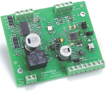
Driver de motores paso a paso para el ElektorBus

Gerber file
CAM/CAD data for the PCB referred to in this article is available as a Gerber file. Elektor GREEN and GOLD members can exclusively download these files for free as part of their membership. Gerber files allow a PCB to be produced on an appropriate device available locally, or through an online PCB manufacturing service.
Elektor recommends the Elektor PCB Service service from its business partner Eurocircuits or AISLER as the best services for its own prototypes and volume production.
The use of our Gerber files is provided under a modified Creative Commons license. Creative Commons offers authors, scientists, educators and other creatives the freedom to handle their copyright in a more free way without losing their ownership.
Components
The BOM (Bill of Materials) is the technically exhaustive listing of parts and other hardware items used to produce the working and tested prototype of any Elektor Labs project. The BOM file contains deeper information than the Component List published for the same project in Elektor Magazine. If required the BOM gets updated directly by our lab engineers. As a reader, you can download the list here.
Want to learn more about our BOM list? Read the BOM list article for extra information.
Component list
Resistencias:
R1 = 0 Ohm
R2, R12, R15 = 39 kOhm
R3 = 680 Ohm
R4 = 100 Ohm
R5, R23 = 100 kOhm
R6 a R11 = 1R0 (Vishay CRCW25121R00FKEG)
R13, R19, R20 = 10 kOhm
R14 = 10 Ohm
R16, R18 = 0 Ohm (ver cuadro de texto)
R17, R21 = no montado (ver cuadro de texto)
R22 = 120 Ohm
R24, R25 = 10 kOhm opcional (ver cuadro de texto)
R26 = 4k7
P1 = potenciómetro de 10 kOhm (POT4MM-2)
Condensadores:
(0805, si no se especifica otra)
C1 = 68 µF / 10 V, tántalo (AVX TPSB686K010R0600)
C2 = 470 µF / 35 V, electrolítico (Panasonic EEEFK1V471AQ)
C3, C5, C8, C12 = 10 nF
C4 = 1000 µF / 50 V, electrolítico (Panasonic EEVFK1H102M)
C6 = 68 nF
C7 = 220 nF
C9 = 5n6
C10, C11 = 1 nF
C13, C14, C17 = 10 µF / 6V3 (AVX TCJA106M006R0300)
C15, C16 = 100 nF
C18, C19 = 22 pF
Inductancias:
L1 = 47 µH (744773147)
Semiconductores:
D1 = Schottky 1 A / 60 V (B160-13-F)
D2, D3, D6 = diodo 1N4148
D4, D5 = diodo Zener 5V1 (BZX384-B5V1)
T1 = BC849B, SOT-23
LED1 = LED verde (5988270107F)
IC2 = L6208D (SO24)
IC3 = ATmega328P-AU
IC4 = LT1785CS8
Varios:
JP1 = conector tipo pin-header de 2x3 pines, 2,54 mm
JP2, JP3 = conector tipo pin-header de una fila, 2,54 mm
K1 a K9 = clema de tornillos para montaje sobre placa, 5,08 mm
S1 = pulsador (Omron B3S-1000)
X1 = oscilador de cuarzo de 16 MHz, 50 ppm, 16 pF (Epson Toyocom FA-365)
Placa referencia 120509-1


Discussion (0 comments)