Article
Modular RF Link using Manchester Code (1)
Part 1: Hardware
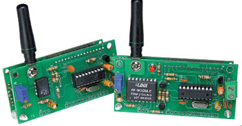
When there is a need to send data to a distant point without using a wired connection, either because the location’s infrastructure does not allow a twisted pair to link both extremes, or just because one or both of the connected circuits are intended to be portable, or simply wireless, there are several ways to solve this, each of them with its own pros and cons. Let’s investigate, solve and solder.
Materials
Gerber file
CAM/CAD data for the PCB referred to in this article is available as a Gerber file. Elektor GREEN and GOLD members can exclusively download these files for free as part of their membership. Gerber files allow a PCB to be produced on an appropriate device available locally, or through an online PCB manufacturing service.
Elektor recommends the Elektor PCB Service service from its business partner Eurocircuits or AISLER as the best services for its own prototypes and volume production.
The use of our Gerber files is provided under a modified Creative Commons license. Creative Commons offers authors, scientists, educators and other creatives the freedom to handle their copyright in a more free way without losing their ownership.
PCB
Component list
COMPONENT LIST
Transmitter
R1 = 0Ohm
R2,R6 = 180Ohm
R3 = 470Ohm
R4 = 10Ohm
R5, R9 = 1kOhm
R8 = 680Ohm
C1,C2,C3,C7,C8 = 100nF
C4,C6 = 10µF 25V
C5 = 3.3µF 50V
IC3 = TXM-315-LR, Linx Technologies (418 or 433 MHz version as appropriate)
K2 = 16-pin SIL connector, 0.1’’ pitch
K3 = 3-pin SIL connector, 0.1’’ pitch
LCD1 = 2x16 characters, DEM16217, Elektor Store #120061-71
X1 = 20 MHz quartz crystal
PCB #120049-13
Receiver
Resistors
R1 = not fitted
R2 = 10Ohm
R3,R5,R10 = 1kOhm
R4,R6 = 10kOhm
R7 = 330Ohm
R8, R9 = 180Ohm
P1 = 10kOhm multiturn preset
Capacitors
C1,C2,C3,C7,C8,C9 = 100 nF
C4 = 3.3uF 50V
C5,C6 = 10uF 25V
Semiconductors
D1 = LED, red, 5mm pitch
IC1 = LP2950-30LPR
IC2 = PIC16F628A-I/P
IC3 = RXM-315-LR, Linx Technologies (418 or 433 MHz version as appropriate)
T1,T2 = BC547B
Miscellaneous
ANT = ANT-315-PW-LP, Linx Technologies
K1 = 2-pin PCB screw terminal block, 5mm pitch
K2 = 16-pin SIL connector
K3 = 3-pin SIL connector
LCD1 = 2x16 character, DEM16217, Elektor #120061-71
X1 = quartz crystal, 20 MHz
PCB #120049-24
Discussion (0 comments)