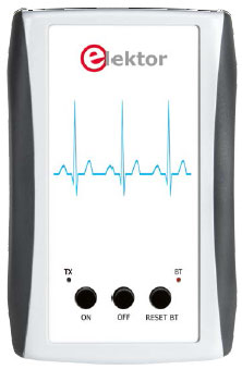
Android Elektorcardioscope (Part 3)
Construction, adjustments, and operating instructions

This is a MEMBER ONLY article. You need a subscription to read this article.
- Unlimited access to online Member Only articles
- 3 new editions Elektor Magazine (digital)
- More than 5000 Gerber files
- 20% member discount on e-books (at elektor.com)
- 10% member discount on Products (at elektor.com)
Available from €5.33 per month.
What is Members Only
Elektor is committed to providing high-quality content on electronics, catering to tens of thousands of paying members. As part of this commitment, Elektor has launched Premium, an initiative that offers exclusive online articles to members sometimes even before they appear in the magazine.
Every day, members can access in-depth articles that showcase the best of Elektor's premium content.
This initiative aims to reward members with early access. Once logged in, members can easily enjoy this exclusive content and engage in discussions about featured projects. While Premium adds to the existing resources available, Elektor will continue to provide a wealth of free information.
Join the Elektor community today to take advantage of Premium and other benefits!
Materials
Component list
Resistors
Default: SMD 0603 shape, 1%
R1,R13,R15,R18,R19,R20,R33,R34,R54 = 10kOhm 0.25W
R2, R12 = 3.3kOhm
R3 = 523kOhm
R4 = 300kOhm
R6 = 150Ohm
R7–R11,R23 = 1kOhm
R14,R53,R55,R56,R57,R59–R62 = 100kOhm
R5,R16,R17,R35 = 1MOhm
R21,R36,R37,R38 = 330kOhm
R22 = 100Ohm
R24,R65 = 390kOhm
R25,R29 = 47MOhm 5%
R26,R30 = 10MOhm
R27,R31 = 2.2MOhm
R28,R32 = 470kOhm
R39,R40,R49–R52 = 47kOhm
R41,R42,R45,R46 = 28.7kOhm
R43,R44 = 1.4MOhm
R47,R48 = 45.3kOhm
R58 = 9.1kOhm
R63,R64 = 27Ohm
P1,P2 = 5kOhm 20% adjustable (Vishay TS53YJ502MR10)
P3 = 2kOhm 20% adjustable (Vishay TS53YJ202MR10)
Capacitors
Default: SMD 0603
C1,C13 = 33µF 6.3V, tantalum (case A)
C2,C4,C7,C9,C12,C14 = 10µF 6.3V, X5R
C3,C5,C6,C8,C10,C15,C21,C22,C23,C24,C39,C40,C41,C42,C43,C44 = 100nF 25V, X7R
C11,C16,C25,C26,C31–C38 = 1µF 10V, X5R
C17–C20 = 1nF 50V, X7R*
C27, C29 = 470pF 50V, 5%,NP0
C28, C30 = 47nF 25V 5%, X7R
* C18, C19, C20 are 1 nF 50V, not 100 nF 50V as shown in the schematic.
Inductors
L1 = 4.7µH 20% 0.5A (Wuerth 744032004)
L2–L9 = ferrite bead, 30Ohm @ 100MHz (Murata BLM18PG330SN1D)
Semiconductor
D1, D2 = BAV99S
D3, D4 = LED, red, (PLCC-4)
T1 = PSMN6R5-25YLC NMOSFET
IC1 = PIC24FJ32GA002-I/SS, programmed, Elektor # 120107-41
IC2 = TPS60403DBVT
IC3–IC7 = TLC2252AIDRG4
IC8 = LMC6482AIMX/NOPB
IC9 = DG4053 AEQ-T1-E3
IC10, IC11 = CD74HC4052PW
IC12 = MCP1640BT-I/CHY
IC13 = LTC1981ES5#TRMPBF
Miscellaneous
K1 = 5-pin pinheader, 0.1’’ pitch
K2 = 6-pin pinheader, 0.1’’ pitch
K3 = 2-pin pinheader, 0.1’’ pitch
MOD1 = Bluetooth module, Roving Networks/Microchip type RN-42
S1,S2,S3 = pushbutton, Omron type SPNO B3FS-1052) with cap, Omron type B32-2010
Case, Pactec PPL-2AA
PCB, Elektor # 120107-1 or
Assembled module, ready for use, Elektor # 120107-91


Discussion (0 comments)