

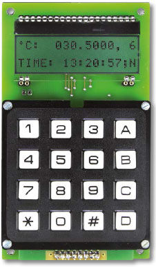
Multichannel Temperature Logger
This is a MEMBER ONLY article. You need a subscription to read this article.
- Unlimited access to online Member Only articles
- 3 new editions Elektor Magazine (digital)
- More than 5000 Gerber files
- 20% member discount on e-books (at elektor.com)
- 10% member discount on Products (at elektor.com)
Available from €5.33 per month.
What is Members Only
Elektor is committed to providing high-quality content on electronics, catering to tens of thousands of paying members. As part of this commitment, Elektor has launched Premium, an initiative that offers exclusive online articles to members sometimes even before they appear in the magazine.
Every day, members can access in-depth articles that showcase the best of Elektor's premium content.
This initiative aims to reward members with early access. Once logged in, members can easily enjoy this exclusive content and engage in discussions about featured projects. While Premium adds to the existing resources available, Elektor will continue to provide a wealth of free information.
Join the Elektor community today to take advantage of Premium and other benefits!
Gerber file
CAM/CAD data for the PCB referred to in this article is available as a Gerber file. Elektor GREEN and GOLD members can exclusively download these files for free as part of their membership. Gerber files allow a PCB to be produced on an appropriate device available locally, or through an online PCB manufacturing service.
Elektor recommends the Elektor PCB Service service from its business partner Eurocircuits or AISLER as the best services for its own prototypes and volume production.
The use of our Gerber files is provided under a modified Creative Commons license. Creative Commons offers authors, scientists, educators and other creatives the freedom to handle their copyright in a more free way without losing their ownership.
Component list
Resistors
R1,R2,R21,R28,R29,R30,R31,R32,R33 = 10kOhm 5% 125mW
R3,R4,R5,R6,R7,R8,R13,R14 = 100Ohm 5% 125mW
R9,R10,R11,R12 = 8.2kOhm 5% 125mW
R15,R16,R17,R22,R23,R24,R25,R26 = 1kOhm 5% 125mW
R18,R19 = 1.5Ohm 5% 100mW
R20 = 18kOhm 5% 125mW
R27 = 56kOhm 5% 125mW
Capacitors
(SMD 0805)
C1,C2,C3,C6,C7 = 100nF 50V 20%
C4 = 1µF 16V electrolytic
C5 = 470nF 25V
C8,C9 = 22pF 50V 5%
C10 = 10µF
C11 = 22µF 10V electrolytic
Semiconductors
D1,D2 = LED, 3mm, low current
T1 = BC850, NPN 45V transistor, SOT-23
IC1 = DS1338Z33+, real time clock, SOIC8
IC2 = PIC18F4520-I/PT, 8-bit MCU, programmed, Elektor Store # 120637-41
IC3 = AP1117E33G, LDO regulator, 3.3V, SOT223
IC4,IC5,IC6,IC7,IC8,IC9 = DS18S20, 1-Wire temperature sensor, TO92 (not on board)
Miscellaneous
Kb1 = MCAK1604NBWB, keypad, 4x4 array, Multicomp
X1 = 32.768kHz quartz crystal, 12.5pF load, 20ppm, 4.1x1.5mm, Abracon ABS09-32.768KHZ-T
X2 = 8MHz quartz crystal, 18pF load, 20ppm, 5x3.2mm, Abracon ABM3-8.000MHZ-D2Y-T
Card1 = uSD (micro SD) connector, Hirose DM3AT-SF-PEJM5(40)
BT1 = CR2032, with PCB mount holder
LCD1 = DOGM162W-A 2x16 character LCD
Backlight EA LED55x31-G
K1 = 6-pin pinheader, right angled, 0.1’’ pitch
K2 = 2-pin pinheader, right angled, 0.1’’ pitch
K3,K4,K5,K6,K7,K8 = 3-pin pinheader or socket, right angled, 0.1’’ pitch
Socket strip 0.1’’ pitch, turned pins, for mounting LCD and keypad
PCB # 120637
Discussion (0 comments)