
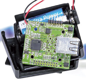
Home and Office Network Tester
Effortless Ethernet connections
Continue reading this article with an Elektor Membership.
Join tens of thousands of engineers and electronics enthusiasts worldwide as a
member. Enjoy access to Elektor Magazine, the Elektor library, exclusive discounts,
early notification about Academy Pro products, and more. Select a membership
today and start exploring everything Elektor has to offer. Log in here if you are already a member.
PRINT (Gold)
- 8x Elektor Magazine (Print)
- 8x Elektor Magazine (Digital)
- Integrated Industry Section
- Access to the Elektor Archive*
- Access to over 5,000 Gerber files
- At least 10% Member Discount on Elektor Store*
Free shipping within the US, UK & Ireland.
*Member discount and unlimited archive access only for full GOLD or GREEN members. Trial members have limited access to the online archive.
DIGITAL (Green)
- 8x Elektor Magazine (Print)
- 8x Elektor Magazine (Digital)
- Integrated Industry Section
- Access to the Elektor Archive*
- Access to over 5,000 Gerber files
- At least 10% Member Discount on Elektor Store*
* Member discount and unlimited archive access only for full GOLD or GREEN members. Trial members have limited access to the online archive.

BUY THIS ARTICLE (PDF)
Gerber file
CAM/CAD data for the PCB referred to in this article is available as a Gerber file. Elektor GREEN and GOLD members can exclusively download these files for free as part of their membership. Gerber files allow a PCB to be produced on an appropriate device available locally, or through an online PCB manufacturing service.
Elektor recommends the Elektor PCB Service service from its business partner Eurocircuits or AISLER as the best services for its own prototypes and volume production.
The use of our Gerber files is provided under a modified Creative Commons license. Creative Commons offers authors, scientists, educators and other creatives the freedom to handle their copyright in a more free way without losing their ownership.
Components
The BOM (Bill of Materials) is the technically exhaustive listing of parts and other hardware items used to produce the working and tested prototype of any Elektor Labs project. The BOM file contains deeper information than the Component List published for the same project in Elektor Magazine. If required the BOM gets updated directly by our lab engineers. As a reader, you can download the list here.
Want to learn more about our BOM list? Read the BOM list article for extra information.
Component list
Resistors
(all 0603)
R1,R2,R3,R7 = 220Ohm 1%
R6,R8 = 10kOhm 1%
R9,R32 = 1.5kOhm 1%
R10,R11 = 4.7kOhm 1%
R12,R19,R20,R21,R22,R23,R24 = 0Ohm, not mounted, see text
R14,R15,R16,R17,R18 = 47kOhm 1%
R30,R31 = 27Ohm 1%
Capacitors
(0603 unless specified otherwise)
C1,C2 = 22pF 5%
C3 = 10nF 10%
C4,C5 = 1nF 10%
C6,C7,C8,C9,C11,C12,C13,C16,C21,C22,C23 = 100nF 20%
C10 = 2.2µF 6.3V 10%, 0805
C17 = 10 µF 6.3V 20%, 0805
C18 = 33pF 5%
C19,C20 = 15pF 5%
Semiconductors
D1 = LED 3mm, red, low current
D2 = LED 3mm, yellow, low current
D3 = LED 3mm, green, low current
IC1 = AT91SAM7S512
IC2 = XC6206P332
IC3 = 24LC256
IC4,IC5 = 65HVD10
IC6 = 74AHC1GU04
IC7 = MCP130
Miscellaneous
K1 = RJ45 jack with integrated magnetics (Stewart Connector type SI-60002-F)
K2 = 2-pin pinheader, 0.1’’ pitch
K3 = 4-pin pinheader, 0.1’’ pitch
K4 = 20-pin (2x10) pinheader, 0.1’’ pitch
K5 = 6-pin pinheader, 0.1’’ pitch
S1,S2 = tactile switch, 6mm square
X1 = 18.432MHz quartz crystal, 5x3.2mm
Case Hammond 1593PGY
FTDI cable 3V3
PCB # 120052
We buy at:

Discussion (0 comments)