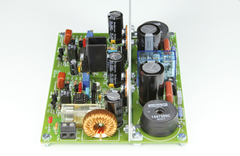
555 Class-D Audio Amplifier
A novel use for an old-timer

This is a MEMBER ONLY article. You need a subscription to read this article.
- Unlimited access to online Member Only articles
- 3 new editions Elektor Magazine (digital)
- More than 5000 Gerber files
- 20% member discount on e-books (at elektor.com)
- 10% member discount on Products (at elektor.com)
Available from €5.33 per month.
What is Members Only
Elektor is committed to providing high-quality content on electronics, catering to tens of thousands of paying members. As part of this commitment, Elektor has launched Premium, an initiative that offers exclusive online articles to members sometimes even before they appear in the magazine.
Every day, members can access in-depth articles that showcase the best of Elektor's premium content.
This initiative aims to reward members with early access. Once logged in, members can easily enjoy this exclusive content and engage in discussions about featured projects. While Premium adds to the existing resources available, Elektor will continue to provide a wealth of free information.
Join the Elektor community today to take advantage of Premium and other benefits!
Gerber file
CAM/CAD data for the PCB referred to in this article is available as a Gerber file. Elektor GREEN and GOLD members can exclusively download these files for free as part of their membership. Gerber files allow a PCB to be produced on an appropriate device available locally, or through an online PCB manufacturing service.
Elektor recommends the Elektor PCB Service service from its business partner Eurocircuits or AISLER as the best services for its own prototypes and volume production.
The use of our Gerber files is provided under a modified Creative Commons license. Creative Commons offers authors, scientists, educators and other creatives the freedom to handle their copyright in a more free way without losing their ownership.
Components
The BOM (Bill of Materials) is the technically exhaustive listing of parts and other hardware items used to produce the working and tested prototype of any Elektor Labs project. The BOM file contains deeper information than the Component List published for the same project in Elektor Magazine. If required the BOM gets updated directly by our lab engineers. As a reader, you can download the list here.
Want to learn more about our BOM list? Read the BOM list article for extra information.
Component list
Resistors
R1,R15 = 100kOhm
R2,R16 = 15kOhm
R3,R17 = 82kOhm
R4,R8,R18,R22 = 1kOhm
R5,R19 = 10kOhm
R6,R20 = 680Ohm
R7,R21,R29 = 2.2kOhm
R9,R23 = 18kOhm
R10,R24 = 470Ohm
R11,R25 = 100Ohm
R12,R26 = 330Ohm
R13,R27 = 8.2Ohm, 1W
R14,R28 = 2.7kOhm
R30 = 56kOhm
R31,R32 = 56Ohm, 1 W
P1,P2 = 2kOhm multiturn preset (Vishay Sfernice T93YB202KT20)
Capacitors
C1,C15 = 2.2µF 50V, 5mm or7.5.mm pitch (e.g. Panasonic ECQV1H225JL)
C2,C16 = 330pF 1%, polystyrene, 7,18mm pitch (e.g. LCR Components EXFS/HR 330PF ±1%)
C3–C6,C8,C10,C17–C20,C22,C24,C30,C32 = 100nF, X7R, 0.2’’ pitch
C7,C9,C21,C23 = 1nF MKT, 5mm pitch
C11,C25,C29 = 1000µF 35 V, radial, 12.5mm dia. 5mm pitch (e.g. Rubycon 35YXF1000MEFC12.5X25)
C12,C26 = 680nF polypropylene, 15mm pitch (e.g. Panasonic ECWF2684JAQ)
C13,C27 = 220nF metallized film (MKT), 5mm pitch
C14,C28, = 2200µF 35V, radial, 18mm diam. 5mm or 7.5mm pitch (e.g. Panasonic EEUTP1V222)
C31 = 10µF 100V, radial, 6.3mm diam., 2.5mm pitch
C33 = 47µF 35V, radial, 8.5mm max. diam., 2.5mm pitch
Inductors
L1,L2 = 47µH, 21mOhm/8.5A, pot core type (Murata Power Solutions 1447385C)
L3 = 100µH, 35mOhm/5A ring core type (Würth Elektronik 7447070)
Semiconductors
D1–D8 = 1N5819
D9,D10 = LED, red, 2x5mm rectangular
D11 = LED, red, 3mm
D12 = 15V/0.5W zener diode
D13 = 1N4148
T1,T3,T10,T12,T19 = BC547C
T2,T4,T11,T13 = BC557C
T5,T14 = BD139
T6,T15 = BD140
T7,T16 = 2N2222
T8,T9,T17,T18 = IRF530
IC1,IC2 = TLC555CP
IC3 = 7815
Miscellaneous
K1,K2 = 2-pin pinheader, 0.1’’ pitch
K3,LS1,LS2 = 2-way PCB screw terminal block, 0.2’’ pitch
RE1 = Relay, 24V, 1200Ohm, 8A, DPDT-CO (e.g. Finder 40.52.7.024.0000)
F1 = glass fuse, 2A(T), slow-blow, with PCB mount holder and cover
TP1,TP2 = 1 pin of pinheader
HS1 = heat sink for MOSFETs, aluminum plate 130 x 50 mm (5.1 x 2 inch), 1-2mm thick
4 x isolating washers for TO-220 case (e.g. Bergquist SIL-PAD K-10, .006’’, TO-220)
4 x isolating bush, 3mm
Heat sink for IC3, 30K/W (e.g. Fischer Elektronik SK 12 SA 32)
Switch-mode power supply, sec. 24V, 2.5A min.
PCB # 130144-1 [1]


Discussion (0 comments)