

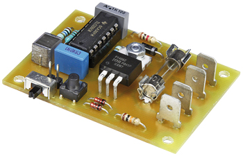
Zero-Electrolytics 555 Timer
The more resistance the better
This is a MEMBER ONLY article. You need a subscription to read this article.
- Unlimited access to online Member Only articles
- 3 new editions Elektor Magazine (digital)
- More than 5000 Gerber files
- 20% member discount on e-books (at elektor.com)
- 10% member discount on Products (at elektor.com)
Available from €5.33 per month.
What is Members Only
Elektor is committed to providing high-quality content on electronics, catering to tens of thousands of paying members. As part of this commitment, Elektor has launched Premium, an initiative that offers exclusive online articles to members sometimes even before they appear in the magazine.
Every day, members can access in-depth articles that showcase the best of Elektor's premium content.
This initiative aims to reward members with early access. Once logged in, members can easily enjoy this exclusive content and engage in discussions about featured projects. While Premium adds to the existing resources available, Elektor will continue to provide a wealth of free information.
Join the Elektor community today to take advantage of Premium and other benefits!
Materials
Gerber file
CAM/CAD data for the PCB referred to in this article is available as a Gerber file. Elektor GREEN and GOLD members can exclusively download these files for free as part of their membership. Gerber files allow a PCB to be produced on an appropriate device available locally, or through an online PCB manufacturing service.
Elektor recommends the Elektor PCB Service service from its business partner Eurocircuits or AISLER as the best services for its own prototypes and volume production.
The use of our Gerber files is provided under a modified Creative Commons license. Creative Commons offers authors, scientists, educators and other creatives the freedom to handle their copyright in a more free way without losing their ownership.
Component list
Resistors
R1 = 1GOhm 0.25W 10%; TE Connectivity type RGP0207CHK1G0
R2,R3 = 10MOhm
R4 = 1kOhm
R5 = 10kOhm
Capacitors
C1 = 390nF, lead pitch 5mm or 7.5mm
C2 = 680nF, lead pitch 5mm or 7.5mm
C3 = 100nF, lead pitch 5mm or 7.5mm
Semiconductors
D1 = 12V 0.5W zenerdiode
D2 = 1N4007
D3,D4 = 1N4148
T1 = IRF1405ZPBF
IC1 = TLC556CN (DIP14)
Miscellaneous
K1–K4 = spade terminals, Faston, 0.2’’ pitch
JP1 = 2-pin pinheader, 0.1’’ pitch
S1 = slide switch, miniature, 1 C/O contact; C&K Components type OS102011MA1QN1
S2 = pushbutton with make contact, 12V 50mA, 6x6 mm
F1 = fuse, 10A fast, 5 x 20 mm, with PCB mount 15A holders; 2 pcs Cooper Bussmann type 1A3399-10-R
PCB # 130257-1
Discussion (0 comments)
Paul Gallagher 2 years ago
After further investigation I was successful, but only after recognising that the very low discharge leakage specification of the TLC556C is critical (200x lower than most other 555/556 components).
This is not pointed out in the article, leading one to perhaps assume that any 555/556 functionally-equivalent component might do. If the article is ever revised or re-published, I'd recommend to specifically emphasise the critical max discharge off-state current specification of the TLC556C.
All the details of my testing the circuit and finally achieving success are covered in my project #631 notes:
https://leap.tardate.com/electronics101/555timer/longrunning/