

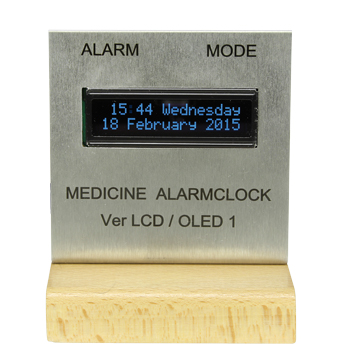
Medication Alarm Clock
With 9 different alarm times
This is a MEMBER ONLY article. You need a subscription to read this article.
- Unlimited access to online Member Only articles
- 3 new editions Elektor Magazine (digital)
- More than 5000 Gerber files
- 20% member discount on e-books (at elektor.com)
- 10% member discount on Products (at elektor.com)
Available from €5.33 per month.
What is Members Only
Elektor is committed to providing high-quality content on electronics, catering to tens of thousands of paying members. As part of this commitment, Elektor has launched Premium, an initiative that offers exclusive online articles to members sometimes even before they appear in the magazine.
Every day, members can access in-depth articles that showcase the best of Elektor's premium content.
This initiative aims to reward members with early access. Once logged in, members can easily enjoy this exclusive content and engage in discussions about featured projects. While Premium adds to the existing resources available, Elektor will continue to provide a wealth of free information.
Join the Elektor community today to take advantage of Premium and other benefits!
Extra info / Update
The alarm day can be a specific weekday are all days
The resolution of the alarm time is 15 minutes
Alarm times are stored in EEPROM
When an alarm signal is not acted upon the alarm signal repeats every 3 minutes for the following 15 minutes
Internal clock with synchronization using a DCF receiver
Monitor function of the received DCF signal
Double-checking of the correctness of the received time
Easy to build, no surface mount components
Component list
Resistors
Default: 0.25W
R1 = 10Ohm
R2,R3,R4 = 10kOhm
R5 = 18kOhm
R10,R11 = 10kOhm trimpot, horizontal
A1-A2 = wire jumper
A3-A4 = wire jumper
Capacitors
C1,C4 = 220µF 16V radial
C2 = 100µF 16V radial
C3 = 10µF 16V radial
C5 = 100nF
C6 = 47nF
C7 = 10nF
C8,C9 = 22pF
C10 = 1µF 16V tantalum
Semiconductors
IC1 = ATMEGA328P, programmed
IC2 = LM386
D1 = 1N4004
Miscellaneous
Display = LCD, 2 x16 characters, or OLED display (e.g. Winstar WEH01602 or EA W162-X3LG)
Q1 = 16MHz quartz crystal
X1 = power supply connector, 2mm center pin
X2 = 2-way PCB terminal block, 0.2” lead pitch
X3 = 3-way PCB terminal block, 0.2” lead pitch
S1,S2 = pushbutton (e.g. Conrad # 700046-89)
DCF77 receiver module (e.g. Conrad # 641138-89)
Discussion (0 comments)
Martien Schot 7 years ago
Martien Schot 7 years ago