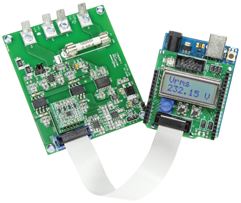
AC/DC Power Meter
With high accuracy and a wide measuring range

This is a MEMBER ONLY article. You need a subscription to read this article.
- Access to Elektor archive and 5,000+ Gerber files
- Receive up to 8 magazines per year (digital and/or paper)
- 10% discount in the Elektor store
Available from €4.95 per month.
What is Members Only
Elektor is committed to providing high-quality content on electronics, catering to tens of thousands of paying members. As part of this commitment, Elektor has launched Premium, an initiative that offers exclusive online articles to members sometimes even before they appear in the magazine.
Every day, members can access in-depth articles that showcase the best of Elektor's premium content.
This initiative aims to reward members with early access. Once logged in, members can easily enjoy this exclusive content and engage in discussions about featured projects. While Premium adds to the existing resources available, Elektor will continue to provide a wealth of free information.
Join the Elektor community today to take advantage of Premium and other benefits!
Extra info / Update
* Maximum input voltage 500 VAC/300 VDC
* Minimum measurable power 0.1 W
* Separate isolated measurement outputs for voltage and current
* Class II insulation between primary and secondary sides
* Measurement data processing by Arduino
* Measured values shown on a two-line LCD
* Displays voltage, current, effective power, reactive power and power factor for AC
* Displays power, voltage and current for DC
Components
The BOM (Bill of Materials) is the technically exhaustive listing of parts and other hardware items used to produce the working and tested prototype of any Elektor Labs project. The BOM file contains deeper information than the Component List published for the same project in Elektor Magazine. If required the BOM gets updated directly by our lab engineers. As a reader, you can download the list here.
Want to learn more about our BOM list? Read the BOM list article for extra information.
Component list
Measurement Board
Resistors
R1 = 0.01Ohm 2W, 1% (Ohmite FC4L64R010FER)
R2,R3 = 22Ohm, 0.25W, 5%, SMD 0805
R4,R31,R33 = 2.20kOhm, 0.125W, 1%, SMD 0805
R5 = 200Ohm, 0.125W, 1%, SMD 0805
R6,R8,R34,R37 = 5.6kOhm, 0.125W, 1%, SMD 0805
R7,R9 = 4.3kOhm, 0.125W, 1%, SMD 0805
R10,R11,R17,R18 = 12Ohm, 0.125W, 1%, SMD 0805
R12,R13,R19,R20,R29,R30 = 47Ohm, 0.125W, 1%, SMD 0805
R14,R15 = 220kOhm, 1.5W, 1%, 500 V, SMD 2512
R16 = 75Ohm, 0.125W, 1%, SMD 0805
R21–R28,R36 = 100kOhm, 0.125W, 1%, SMD 0805
R32 = 39kOhm, 0.125W, 5%, SMD 0805
R35 = 100Ohm, 0.125W, 1%, SMD 0805
Capacitors
C1,C2 = 1nF 50V, 5%, SMD 0805, C0G/NP0
C3,C7,C11,C14,C23,C24,C34,C35 = 100nF 50 V, 10%, SMD 0805, X7R
C4,C15,C17,C19,C21 = 10µF 10V, 10%, SMD 0805, X7R
C5 = 100µF 6.3V, 20%, SMD Case A (1206), tantalum
C6,C10 = 330pF 50V, 5%, SMD 0805, C0G/NP0
C8,C9,C12,C13 = 100nF 50V, 10%, SMD 1206, X7R
C16,C18,C20,C22,C28 = 100nF 25V, 10%, SMD 0603, X7R
C25,C26 = 4.7µF 6.3V, 10%, SMD Case R (0805), tantalum
C27 = 10µF 25V, +80/–20%, SMD 1206, Y5V
C29-C32 = 470pF 50V, 5%, SMD 0805, C0G/NP0
C33 = 470nF 16V, 10%, SMD 0805, X7R
Inductor
L1 = ACM4520-231-2P-T, SMD, common mode choke 3A, 2 x 50mOhm, 230Ohm @100MHz
Semiconductors
D1,D2,D4 = HSMS-2822-TR1G, SMD SOT-23
D3 = SP0502BAHTG, SMD SOT-23
D5,D6 = LED, green, SMD 0805
D7 = BZT52C2V0-7-F, SMD SOD-123 (zener diode 2 V 0.5W)
D8 = PMEG2010AEH, 20V 1A, SMD SOD-123F
IC1,IC4 = AD8639ARZ, SMD SOIC-8
IC2,IC3 = AMC1100DUB, SMD Gullwing-8 (SOP-8)
IC5 = ADuM6000ARWZ, SMD RW-16 (SOIC_W-16)
IC6 = NCP5501DT50G, SMD DPAK3
IC7 = LM311D, SMD SOIC-8
Miscellaneous
Component List
Filter Module
Resistors
R1,R4,R7,R10 = 21.5kOhm 1%, 0.1 W, SMD 0603
R2,R5,R8,R11 = 24.3kOhm, 1%, 0.1 W, SMD 0603
R3,R6,R9,R12 = 23.2kOhm, 1%, 0.1 W, SMD 0603
Capacitors
C1,C4,C7,C10 = 10nF 50V, 5%, C0G/NP0 or X7R, SMD 0603
C2,C5,C8,C11 = 22nF 50V, 5%, C0G/NP0 or X7R, SMD 0603
C3,C6,C9,C12 = 1.5nF 50V, 5%, C0G/NP0 or X7R, SMD 0603
C13,C14,C15,C16 = 100nF 50V, 10%, X7R, SMD 0603
Semiconductors
IC1,IC2,IC3,IC4 = OPA377AIDBVT
Miscellaneous
K1,K2 = 5-pin connector, 0.1’’ pitch
K3,K4 = 5-pin pinheader, 0.1’’ pitch
PCB # 140169-2


Discussion (0 comments)
DAVID MUNOZ 4 years ago
I would like to order a PCB to make this project but only the PDF is provided here.
Can you provide the Gerber file? I don't see this board in the Elektor store either - will it be made available?
Regards,
Dave