Article
Compact 60-watt Amplifier
Cheap & cheerful design packs a punch

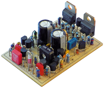
It may not be the highest of Hi-Fi but at only 38x56 mm this low-cost discrete design is smaller and cheaper than IC modules of similar power, yet still delivers excellent sound quality, making it ideal for in-car audio, domestic subwoofers, smartphone/tablet speakers or multi-channel AV...
Materials
Extra info / Update
Specifications
Input sensitivity: 0.2 Vrms (alternatively 1Vrms; see text)
Input impedance: 7 kOhm (or 14 kOhm with lower gain option; see text)
Sinewave power: 4 Ohm 60 W, THD+N = 1%
8 Ohm 36 W, THD+N = 1%
Bandwidth: 20Hz – 80kHz (-3dB)
Signal to noise ratio: >90 dBA
THD + noise: 0.045% at 1 kHz (10 W/4 Ohm)
Damping factor: >250 (1 kHz)
(>1300 at lower gain – see text)
Quiescent current: ˜33 mA (complete amplifier)
Component list
Components List
Resistors
R1 = 2.2kOhm (4.7kOhm)
R3,R5,R6 = 2.2kOhm
R2 = 4.7kOhm (10kOhm)
R4,R13 = 470kOhm (180kOhm)
R7,R8 = 1kOhm
R9,R10 = 5.6kOhm
R11 = 8.2kOhm
R12 = 3.3kOhm
R14,R15 = 100Ohm
R16,R31 = 10kOhm
R17,R20 = 390Ohm
R18,R19 = 270Ohm
R21–R28 = 1Ohm 0.6W
R29,R30 = 3.9Ohm 0.6W
RV1 = 2kOhm preset, vertical
Optional: 2 pcs 150Ohm 4W resistor for use during setup
Capacitors
C1 = 1µF (0.47µF)
C2 = 1nF (560pF)
C3,C4 = 39pF
C5,C6,C8,C10 = 0.1µF
C7,C9 = 470µF 35V radial
() = value for lower gain
Inductors
L1 = 10 turns 1-mm diameter enameled copper wire, inside diameter 5mm
Semiconductors:
D1,D2 = 1N4148
LD1, LD2 = 2mm x 5mm 2.1Vf red LEDs
TR1,TR5,TR6,TR7,TR11 = BC560C
TR2, R3,TR4,TR8,TR9,TR10 = BC550C
TR12 = BDW93C
TR13 = BDW94C
Miscellaneous:
Heatsink (see text)
Mounting kits for TR12 and TR13
9 wire links on PCB
PCB
Suitable power supply, including 2A quick-blow fuses in ±24V lines (see text for recommendations)


Discussion (0 comments)