

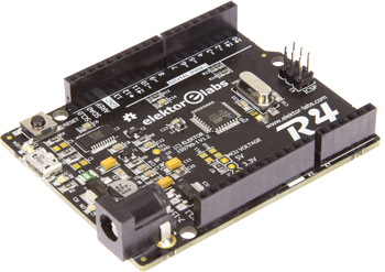
Elektor Uno R4
Four pins make all the difference
This is a MEMBER ONLY article. You need a subscription to read this article.
- Access to Elektor archive and 5,000+ Gerber files
- Receive up to 8 magazines per year (digital and/or paper)
- 10% discount in the Elektor store
Available from €4.95 per month.
What is Members Only
Elektor is committed to providing high-quality content on electronics, catering to tens of thousands of paying members. As part of this commitment, Elektor has launched Premium, an initiative that offers exclusive online articles to members sometimes even before they appear in the magazine.
Every day, members can access in-depth articles that showcase the best of Elektor's premium content.
This initiative aims to reward members with early access. Once logged in, members can easily enjoy this exclusive content and engage in discussions about featured projects. While Premium adds to the existing resources available, Elektor will continue to provide a wealth of free information.
Join the Elektor community today to take advantage of Premium and other benefits!
Gerber file
CAM/CAD data for the PCB referred to in this article is available as a Gerber file. Elektor GREEN and GOLD members can exclusively download these files for free as part of their membership. Gerber files allow a PCB to be produced on an appropriate device available locally, or through an online PCB manufacturing service.
Elektor recommends the Elektor PCB Service service from its business partner Eurocircuits or AISLER as the best services for its own prototypes and volume production.
The use of our Gerber files is provided under a modified Creative Commons license. Creative Commons offers authors, scientists, educators and other creatives the freedom to handle their copyright in a more free way without losing their ownership.
Extra info / Update
• ATmega328PB @ 16 MHz
• 2 x UART
• 2 x I²C
• 2 x SPI
• 9 PWM outputs
• 8 analog inputs
• 24 GPIO pins
• On-board 5 V and 3.3 V voltage regulators
• Arduino compatible Boards package
• Open source, open hardware design.
Component list
Resistors
R7 = 0Ohm
R2,R3 = 27Ohm
R1,R4,R5,R12,R13,R14 = 1kOhm
R6,R8 = 10kOhm
R9,R10,R11 = 0Ohm
Capacitors
Default: 0805
C16,C17 = 22pF
C2,C3 = 47pF
C5,C6,C7,C8,C12,C13,C14,C15,C18 = 100nF
C10 = 1µF
C4,C9,C11 = 10µF, 10V, tantalum, case A
C1 = 47µF, 25V, electrolytic, 6.3mm diam.
Inductor
L1 = 10 µH, SMD 0805
Semiconductors
D1 = MBR120
D2, D3 = BAT54
IC1 = LD1117AS50
IC2 = FT231XS
IC3 = LD1117AS33
IC4 = ATmega328PB-AU
LED1 = green
LED2 = yellow
LED3 = red
LED4 = blue
T1 = TSM2307CX
T2 = 2N7002
Miscellaneous
F1 = PTC, 500 mA
JP1 = 3-pin pinheader, 0.1’’ pitch, right angled
Jumper for JP1
K1 = Micro USB type B receptacle
K2 = barrel jack, 1.95mm center pin
K5 = 12-way pinheader socket, 0.1’’ pitch
K4 = 10-way pinheader socket, 0.1’’ pitch
K6 = 8-way pinheader socket, 0.1’’ pitch
K7 = 6-way pinheader socket, 0.1’’ pitch
K3 = 6-pin (2x3) pinheader, 0.1’’ pitch
S1 = tactile switch, 6x6.2 mm, SMD
X1 = 16 MHz quartz crystal
PCB 150790-1 v1.2
Firmware 150790-11
Discussion (0 comments)