Article
Brick-by-Brick Power Supply
modularity = total versatility
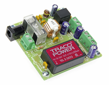
Originally designed as a more compact power supply for our 10-MHz DDS Function Generator the board described in this article can double for other applications when fitted out with different modules. Selecting, combining and optimizing, that’s what this project is all about.
Gerber file
CAM/CAD data for the PCB referred to in this article is available as a Gerber file. Elektor GREEN and GOLD members can exclusively download these files for free as part of their membership. Gerber files allow a PCB to be produced on an appropriate device available locally, or through an online PCB manufacturing service.
Elektor recommends the Elektor PCB Service service from its business partner Eurocircuits or AISLER as the best services for its own prototypes and volume production.
The use of our Gerber files is provided under a modified Creative Commons license. Creative Commons offers authors, scientists, educators and other creatives the freedom to handle their copyright in a more free way without losing their ownership.
PCB
Extra info / Update
* Powered by any laptop power adapter with Vout >19 VDC
* Single-supply output options: 3.3 V or 5 V @ 0.5 A, optionally 1.5 V, 1.8 V, 2.5 V, 3.3 V, 5.0 V, 6.5 V, 9 V, 12 V, 15 V
* Symmetrical-supply output: ±15 V @ 6 W approx., optionally ±9 V, ±12 V
* Industry standard footprint DC/DC modules from Recom and Tracopower
* Zero-SMD, zero–microcontroller design
Component list
Component List
Resistor
R1 = 4.7 kOhm, carbon film, 5%, 0.25W, 250V
Capacitors
C1-C6 = 2.2µF 50V 20%, ceramic Y5V, 0.2’’ pitch
C7 = 4.7µF 50V 20%, 2mm pitch, diam. 6.3mm max.
C8,C10,C11 = 47µF 50V 20%, 2.5mm pitch, diam. 6.3 mm max.
C9,C12,C13 = 100nF 50V 10%, ceramic X7R, 0.2’’ pitch
Inductors
L1 = 4.7µH, 3.05A, 80mOhm, 10%, radial, 5mm pitch, e.g. Epcos B82144B2472K000
L2 = 600µH, 2A, 2 x 50mOhm, common-mode choke, 17.5x14 mm, Kemet SC-02-06G
Semiconductors
D1-D5 = 1N4007 (1000V, 1A)
LED1 = LED, green, 3mm
MOD1 = R-87E3.3-0.5, Recom (3.3V, 0.5A)
MOD2 = TEL 5-2423 Traco Power (5W, ±15 V)
Miscellaneous
K1 = DC barrel jack, 1.95mm pin, 12V, 3A
K2,K3 = PCB screw terminal block, 2-way, 0.2’’ pitch
K4 = PCB screw terminal block, 3-way, 0.2’’ pitch
JP1 = 2-pin pinheader, vertical, 0.1’’ pitch
F1 = fuseholder, 20x5mm, 500V, 10A
F1 = fuseholder cover, 20x5 mm
F1 = fuse, cartridge, 1A slow blow, 20x5mm
PCB # 150464 v. 1.1 from the Elektor Store
Discussion (0 comments)