

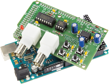
Voltage Tracker for Oscilloscope
Slow-timebase measurements on your oscilloscope using an Arduino shield
This is a MEMBER ONLY article. You need a subscription to read this article.
- Access to Elektor archive and 5,000+ Gerber files
- Receive up to 8 magazines per year (digital and/or paper)
- 10% discount in the Elektor store
Available from €4.95 per month.
What is Members Only
Elektor is committed to providing high-quality content on electronics, catering to tens of thousands of paying members. As part of this commitment, Elektor has launched Premium, an initiative that offers exclusive online articles to members sometimes even before they appear in the magazine.
Every day, members can access in-depth articles that showcase the best of Elektor's premium content.
This initiative aims to reward members with early access. Once logged in, members can easily enjoy this exclusive content and engage in discussions about featured projects. While Premium adds to the existing resources available, Elektor will continue to provide a wealth of free information.
Join the Elektor community today to take advantage of Premium and other benefits!
Gerber file
CAM/CAD data for the PCB referred to in this article is available as a Gerber file. Elektor GREEN and GOLD members can exclusively download these files for free as part of their membership. Gerber files allow a PCB to be produced on an appropriate device available locally, or through an online PCB manufacturing service.
Elektor recommends the Elektor PCB Service service from its business partner Eurocircuits or AISLER as the best services for its own prototypes and volume production.
The use of our Gerber files is provided under a modified Creative Commons license. Creative Commons offers authors, scientists, educators and other creatives the freedom to handle their copyright in a more free way without losing their ownership.
Component list
Resistors
R1,R5 = 1kOhm 5%, 0.25W
R2,R3,R4 = 5.11kOhm 1%, 0.25W, metal film
Capacitors
C1–C7,C9,C11 = 100nF 50V, X7R, 0.2’’ pitch
C8,C10,C12 = 100µF 25V, radial, 0.1’’ pitch
Semiconductors
D1,D2 = 1N4148
LED1 = red, 3mm
IC1 = DAC0808LCN, DIP16
IC2 = MCP601-I/P, DIP8
IC3 = ICL7660CPAZ, DIP8
Miscellaneous
K1, K2 = 8-pin pinheader
K3 = 2-pin pinheader
K7,K8 = BNC socket, PCB mount, right angled
K5 = 6-pin pinheader
K6 = 36-pin (2x18) pinheader
S1–S4 = pushbutton, 6x6 mm, PCB mount
IC sockets for IC1,IC2,IC3
Two coax cables with BNC plugs
PCB # 150422-1 from Elektor Store
Arduino Mega, # 140566-93 from Elektor Store
Caution: all pinheaders to be mounted at PCB underside
Discussion (0 comments)
barnicks 8 years ago
barnicks 8 years ago