

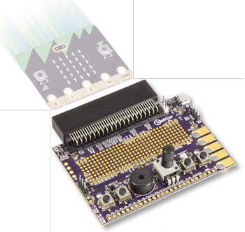
Dock for BBC micro:bit
“Base to micro:bit, you are cleared to dock.”
This is a MEMBER ONLY article. You need a subscription to read this article.
- Unlimited access to online Member Only articles
- 3 new editions Elektor Magazine (digital)
- More than 5000 Gerber files
- 20% member discount on e-books (at elektor.com)
- 10% member discount on Products (at elektor.com)
Available from €5.33 per month.
What is Members Only
Elektor is committed to providing high-quality content on electronics, catering to tens of thousands of paying members. As part of this commitment, Elektor has launched Premium, an initiative that offers exclusive online articles to members sometimes even before they appear in the magazine.
Every day, members can access in-depth articles that showcase the best of Elektor's premium content.
This initiative aims to reward members with early access. Once logged in, members can easily enjoy this exclusive content and engage in discussions about featured projects. While Premium adds to the existing resources available, Elektor will continue to provide a wealth of free information.
Join the Elektor community today to take advantage of Premium and other benefits!
Gerber file
CAM/CAD data for the PCB referred to in this article is available as a Gerber file. Elektor GREEN and GOLD members can exclusively download these files for free as part of their membership. Gerber files allow a PCB to be produced on an appropriate device available locally, or through an online PCB manufacturing service.
Elektor recommends the Elektor PCB Service service from its business partner Eurocircuits or AISLER as the best services for its own prototypes and volume production.
The use of our Gerber files is provided under a modified Creative Commons license. Creative Commons offers authors, scientists, educators and other creatives the freedom to handle their copyright in a more free way without losing their ownership.
Component list
Resistor (1%, 0.1 W, 0603)
R3-R7,R17,R20,R23-R32 = 0Ohm
R19 = 0Ohm, not mounted
R16 = 100Ohm
R2,R9-R12,R33,R34 = 100kOhm
R13, R14, R18, R21, R22 = 150Ohm
R15 = 49.9Ohm (1206)
R1 = 698kOhm
R8 = 10kOhm potentiometer, linear
Capacitor
C1,C2,C4,C5,C6 = 1µF (0603)
C7,C8,C9 = any value, 1206, 0.85mm height
Semiconductor
D2 = 1N5819HW-7-F
D1 = IR67-21C/TR8 (IR diode)
U1 = MCP1824-ADJE/OT
U2 = LCD NHD-C0220BiZ-FS(RGB)-FB-3V NNP (optional)
D3 = LED, blue, 0603
Q1,Q2,Q4,Q5,Q6 = DMG1012UW
Q3 = PT91-21B/TR7
Miscellaneous
J6 = Edge connector socket, 2x40, 0.05” pitch
J7 = 25-pin pin header, 0.1” pitch
J3,J4 = 2-pin pin header, 0.1” pitch
J5,J8 = 3-pin pin header, 0.1” pitch
J2 = USB micro B connector
BZ1 = Piezo buzzer
S1,S2,S3,S4 = Tactile switch, 6x6mm
PCB 160274-1 rev3.2
Discussion (0 comments)