

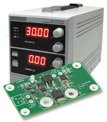
Soft Start for PSU
Be nice to your power supply – and its load
This is a MEMBER ONLY article. You need a subscription to read this article.
- Unlimited access to online Member Only articles
- 3 new editions Elektor Magazine (digital)
- More than 5000 Gerber files
- 20% member discount on e-books (at elektor.com)
- 10% member discount on Products (at elektor.com)
Available from €5.33 per month.
What is Members Only
Elektor is committed to providing high-quality content on electronics, catering to tens of thousands of paying members. As part of this commitment, Elektor has launched Premium, an initiative that offers exclusive online articles to members sometimes even before they appear in the magazine.
Every day, members can access in-depth articles that showcase the best of Elektor's premium content.
This initiative aims to reward members with early access. Once logged in, members can easily enjoy this exclusive content and engage in discussions about featured projects. While Premium adds to the existing resources available, Elektor will continue to provide a wealth of free information.
Join the Elektor community today to take advantage of Premium and other benefits!
Gerber file
CAM/CAD data for the PCB referred to in this article is available as a Gerber file. Elektor GREEN and GOLD members can exclusively download these files for free as part of their membership. Gerber files allow a PCB to be produced on an appropriate device available locally, or through an online PCB manufacturing service.
Elektor recommends the Elektor PCB Service service from its business partner Eurocircuits or AISLER as the best services for its own prototypes and volume production.
The use of our Gerber files is provided under a modified Creative Commons license. Creative Commons offers authors, scientists, educators and other creatives the freedom to handle their copyright in a more free way without losing their ownership.
Component list
Resistors
R1 = 100Ohm, thick film, 5%, 0.1W, 150V
R2,R7 = 10kOhm, thick film, 5%, 0.1W, 150V
R3,R4 = 1kOhm, thick film, 5%, 0.1W, 150V
R5 = 3.6kOhm, 1%, 125mW, 150V, 0805
R6 = 240kOhm, 1%, 125mW, 150V, 0805
Capacitors
C1 = 100nF, 50V, X7R, 0805
C2 = 22µF, 10V, X5R, 20%, 1206
C3 = 1µF, 50V, 10%, X7R, 1206
C4 = 220nF, 50V, X7R, 0805
C5 = 1nF, 50V, 10%, X7R, 0603
Semiconductors
D1,D2 = 1N4148WS (100V, 200mA, 4ns)
LED1 = bicolour red/green, 3mm
T1,T2 = NVD6824NLT4G (n-channel MOSFET, 100V, 41A)
T3 = 2N7002 (60V, 250mA, 300mW, Vgs = 4.5V, RDS(on) = 1Ohm)
IC1 = MAX5024 (voltage regulator, 5V, 150mA, LDO)
IC2 = MAX16126TCA+ (voltage supervisor)
IC3 = MAX16054AZT+T (pushbutton debouncer)
K1 = 2-way PCB screw terminal block, 0.2" pitch, 630V
K2A = see text
K2B = 2-way PCB screw terminal block, 0.2" pitch, 630V
K3,K4 = 2-pin (1×2) pinheader
S1 = pushbutton NO (e.g. Multicomp R13-24A-05-BR)
Miscellaneous
PCB 160383-1 V1.1 with IC2 premounted (see text)
Discussion (0 comments)
marcosbuydid 2 years ago
Content Director, Elektor 2 years ago
Mathias_Claussen(Elektor) 2 years ago
if you have a short in your load the FETs will still transport current. There is a thermal shutdown within the design but if this will kick in before the FETs get damaged is hard to say and depends on you power supply and the current you will draw with yout short.
Best Regards
Mathias Claußen
EN0196684ID 1 year ago
There was mentioned that the maximum current is 5A.
Is it possible to increase it to 10A or a bit more and how?
J.F. Simon, Elektor 1 year ago
EN0196684ID 1 year ago
Thanks for the detailed explanation!