

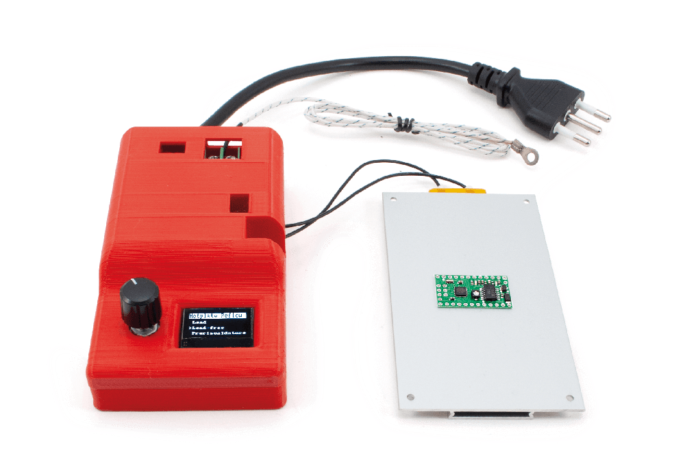
Mini Reflow Plate
For Assembling or Repairing Small SMD Circuits
This is a MEMBER ONLY article. You need a subscription to read this article.
- Unlimited access to online Member Only articles
- 3 new editions Elektor Magazine (digital)
- More than 5000 Gerber files
- 20% member discount on e-books (at elektor.com)
- 10% member discount on Products (at elektor.com)
Available from €5.33 per month.
What is Members Only
Elektor is committed to providing high-quality content on electronics, catering to tens of thousands of paying members. As part of this commitment, Elektor has launched Premium, an initiative that offers exclusive online articles to members sometimes even before they appear in the magazine.
Every day, members can access in-depth articles that showcase the best of Elektor's premium content.
This initiative aims to reward members with early access. Once logged in, members can easily enjoy this exclusive content and engage in discussions about featured projects. While Premium adds to the existing resources available, Elektor will continue to provide a wealth of free information.
Join the Elektor community today to take advantage of Premium and other benefits!
Component list
Component List
Resistors
R1…R3 = 470 Ω
R2 = 10 kΩ
R4…R5 = 47 kΩ
Modules
U1 = Arduino Nano
PS1 = 3WMA2205V (PSU Module)
BRD1 = MODMAX6675 (for K-type thermocouples)
LCD1 = OLEDGVSCSD (0.96″ OLED)
Miscellaneous
BZ1 = 5 V buzzer (without oscillator)
Header strip, female, 4 pins
Header strip, female, 15 pins
Header strip, female, 5 pins
Screw terminal block, 2 poles
Rotary encoder with pushbutton
Heating element: 400WPTCRISC on https://futuranet.it
also available from Aliexpress and Ebay by searching for "400W PTC heating plate" (choose 400 W version, and the correct voltage for your country)
Discussion (0 comments)
white rabbit 1 year ago
What size is it?
How many watts is it rated for?
What is the maximum temperature it can reach?
Is it resistive or PTC?
What is the manufacturer part number or other identification?
What is the procurement source?
Addition of this information will complete an otherwise excellent and useful construction article.
Phillip Norman 1 year ago
J.F. Simon, Elektor 1 year ago
Phillip Norman 1 year ago
Southerner 1 year ago
Thank you.
J.F. Simon, Elektor 1 year ago
Southerner 1 year ago
J.F. Simon, Elektor 1 year ago
Southerner 1 year ago
Thank you.
Southerner 1 year ago
J.F. Simon, Elektor 1 year ago
Unfortunately, the STL files were not provided to us, I'm sorry for the inconvenience. We don't sell the enclosure either. I would recommend that you use a plastic electrical enclosure (which can be bought in many hardware / home improvement stores), big enough to also contain the external SSR required to drive the heating element. That way, the overall wiring can be neater (one mains cable input, two wires for the output to the heating element)
Guy Melon 1 year ago
How did you fixed / mounted the thermocouple on the heating element ?
J.F. Simon, Elektor 1 year ago
the author suggests inserting the end of the thermocouple in a ring terminal and crimping "without exaggeration" (it may be hard to get it just right) and using a screw to bolt it to the plate. However, the only holes in the heating plate are near the edges; not the ideal spot to check the temperature. It may be possible to drill and tap a tiny hole in the middle of the heating plate, but I would advise against it as there is a high risk of drilling into the resistive wire inside; thus risking both damage to the plate and exposure to electric shock. The second option mentioned by the author (sticking the thermocouple to the PCB with kapton tape) is better and gives a more accurate temperature reading, provided that you stick it well enough. A third and, IMHO even better solution is to use a small piece of scrap PCB that you cut from an old board (at least 2 layers and with a some ground planes, to be representative of modern electronics), choose a thermocouple that's thin enough, and place it in a small hole in that scrap PCB, with a dab of thermal paste. And then you place this “dummy PCB-probe” right next to the PCB you are soldering. Then you get a good estimate of the temperature of your “real” PCB, and you don’t need to mess with sticky tape.
Southerner 1 year ago
Thank you.
J.F. Simon, Elektor 1 year ago
Southerner 1 year ago
One thing I would like to see in articles like this are suggestions for enclosures or information about what the author used (if any). Enclosures are often more a problem than the circuit itself.
Thank you.
astroboy 1 year ago
2.- Resistor R1 is connected to PIN 3 of the Fotek SSR-25-DA relay...right?
J.F. Simon, Elektor 1 year ago
1- there are many many part numbers of encoders that could work for that, depending on what you want in terms of shaft length, shaft type, and what's in stock in your favorite parts supplier. (I suspect many generic ones from Ebay/Ali could fit too). You can use the Gerber files (or the snippet attached to this comment) as a reference. I think, for example, Farnell 2663532 should fit.
2. yes, correct. Good luck !
astroboy 1 year ago
Thank you very much for your answer, your comments and the image will be very useful for me...
I will start the mini reflow plate the next days...If there is some relevant observation, I will let you know
Best regards