

Article
A Modular Approach to Sensor Testing
The ESP32-S3-Based Sensor Evaluation Board
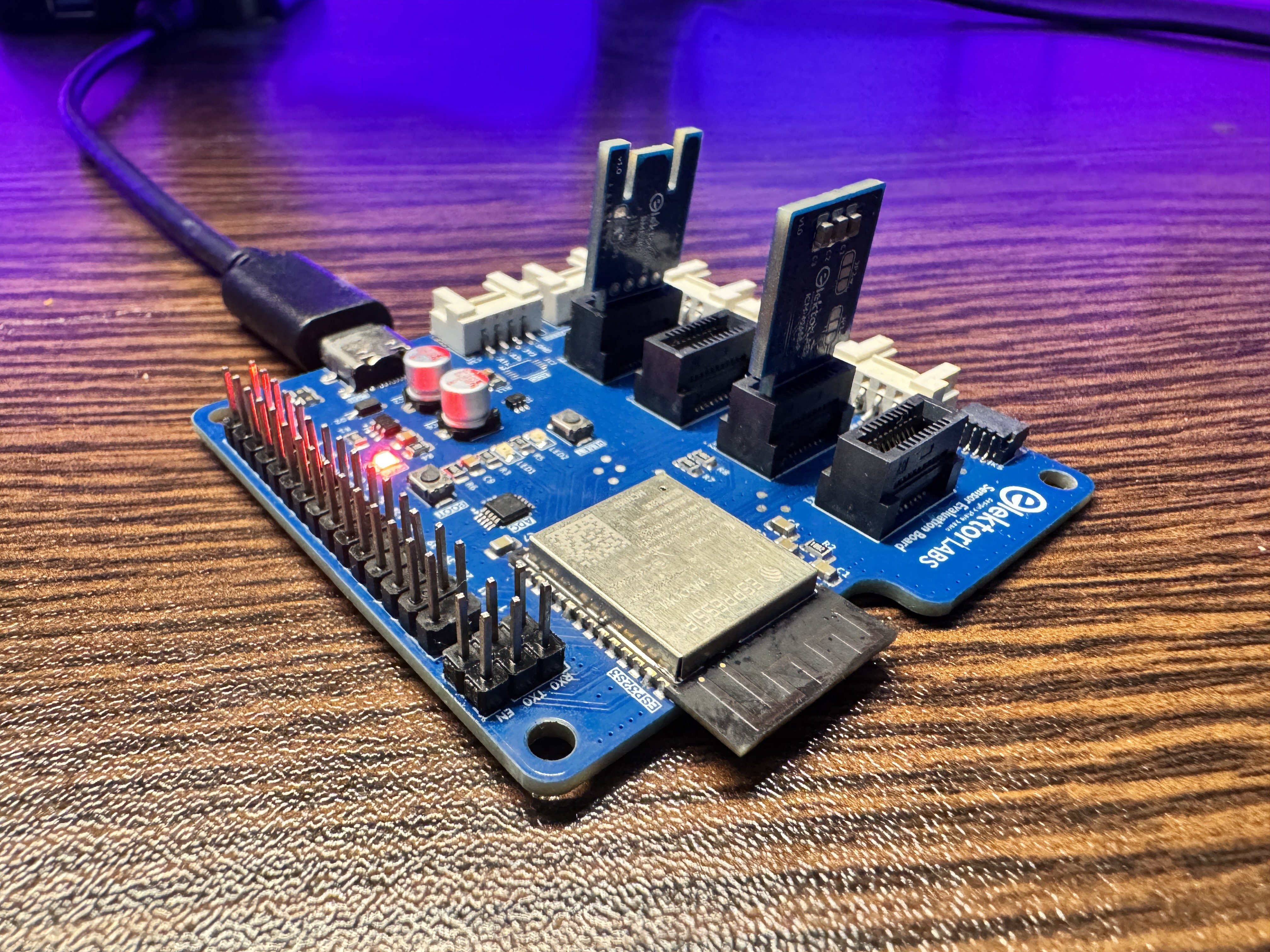
The Sensor Evaluation Board was created to solve the hassle of repeatedly swapping sensors during development. Based on the ESP32-S3, it includes two high-precision ADS1015 ADCs, Grove connectors, and modular edge card slots. These features allow one to effortlessly test and swap sensors, addressing the ESP32’s ADC limitations and ensuring consistent, accurate data for a smoother, more efficient prototyping process.
Materials
Component list
Component List
Resistors
R1 = 100 kΩ
R2, R11, R6, R7, R8 = 10 kΩ
R3, R4, R5 = 100 Ω
R9, R10 = 4.7 kΩ
Capacitors
C1 = 100 nF, 50V
C2, C6 = 22 µF
C3, C4, C7 = 0.1 µF
C5, C8, C9, C10 = 0.01 µF
Semiconductors
D1 = SMF05C.TCT
D2 = 1N5819HW-7-F
D3 = B140HW-7
IC1, IC2 = ADS1015IDGS
IC3 = Regulator TLV75733PDBVR
LED1 = NCD0805A0 (Amber)
LED2 = NCD0805G1 (Green)
LED3 = NCD0805R1 (Red)
MOD1 = ESP32-S3-WROOM-1
Others
SW1, SW2 = Button SKRKAEE020
J1 = 2×3 Pin, 2.54 mm Vertical Header
J2 = 2×15 Pin, 2.54 mm Vertical Header
K1, K2, K3, K4 = 408-52020-000-11 (ept Card Edge Connectors)
K5 = Qwiic Connector
K6, K7, K8, K9, K10 = Grove Connectors
K11 = USB-C GSB1C41110SSHR
Discussion (0 comments)