2 Channel RF power meter with Wifi, Bluetooth, SD card and touch screen
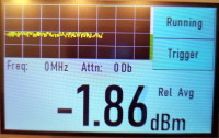
2 Channel power meter up to 10GHz with 92dB dynamic range. Lots of measurement functions. Compatible with almost all power detector chips.
Next version of my previous RF Power meter
https://www.elektormagazine.com/labs/rf-power-meter-with-1mhz-10ghz-bandwidth-and-55db-dynamic-range
Features
https://www.elektormagazine.com/labs/rf-power-meter-with-1mhz-10ghz-bandwidth-and-55db-dynamic-range
Features
- 2 Channels
- Up to 10 GHz range
- Up to 92 dB dynamic range
- Swappable 4 layer RF breakout boards for AD83xx, LT5537, LMV22x, LT8881, etc.
- Compatible with Elector RF Breakout module (160193-91)
- 250 ksps 16 bit ADC per channel
- ESP32 WROVER 16MB Flash, 8MB RAM
- 3.5" LCD with touch screen
- SD Card support
- Wifi
- Bluetooth
- USB
- Realtime clock
- Sync RTC with NTP server
- HTML interface
- Downloading measurement data to PC
- SWR measurement
- Trigger input
- Scope display
- Trigger modes: normal, single, auto
- Data logging to memory and SD Card
- Measurements: Min, Max, Average, modulation depth, statistics, etc.
- Encoder with button
- Low noise power supplies
- SCPI commands
Updates from the author
breedj 4 years ago
I'm know in the progress of writing the first lines of code for the firmware. I'm currently doing that using Platform IO with Visual Studio Code and the Arduino framework after trying some other frameworks and the EDP-IDF as well. The arduino framework might be the best choise for this project.
I had some trouble with the SPI interface. Information on the internet about the ESP32 is not always correct. A lot of information says the SPI clock can be up to 40MHz and even up 80MHz. That is not entirely true. These frequencies are only when writing to a slave. When reading data from a slave the maximum us 26.6MHz. It also takes 3us to start the transaction and another 3us to end it. Eventually I managed to get around 100ksps from the ADC, 2 channels simultaneously. Unfortunatly I am not able the use the full 250ksps bandwidth of the ADC. I will need an FPGA for that, but I think 100ksps is enough for most of us.
I'm currently busy writing the data aqcuisition part with sample averaging and the triggering for the oscilloscope mode. I already have a bit experience with that after writing the software for the Network Connected Signal Analyzer project a few years ago.
My aim is to get a measurement resolution of 0.01db with this project.
breedj 5 years ago
I've done some tests with a ESP32 WROVER. It has lots of flash and RAM and also Wifi, Bluetooth and native SD card support. For the LCD I first tried a Nextion LCD, but it is too slow. I now use a standard 3.5" LCD with a ILI9341 driver and touch screen and am using the littlevGL library.
I will post a project update now and then to keep you informed. Please leave comments if you have any ideas for me to implement. I have not started with the software development yet.
Breakout board AD8318 (19kb)
Power meter (54kb)
Breakout pcb (624kb)