

4-Channel USB-to-Serial Converter + 3-Port USB Hub [140033]
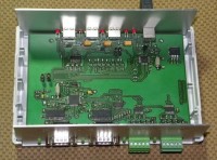
Cool project. Offers a serial to USB bridge featuring two full 9-pin RS-232 ports plus two RS-422 ports (full-duplex). In addition to this the device also integrates a USB hub, giving three supplemental USB ports. Jumpers allow bypassing of the USB hub, making it easy to test the serial bridge all by itself.
Cool project. Offers a serial to USB bridge featuring two full 9-pin RS-232 ports plus two RS-422 ports (full-duplex). In addition to this the device also integrates a USB hub, giving three supplemental USB ports. Jumpers allow bypassing of the USB hub, making it easy to test the serial bridge all by itself.
The circuit was designed by Sébastien Guerreiro de Brito who proposed it to us.
We at Elektor.Labs have cleaned up the PCB, fixed some BOM issues and added a few extras:
- Shield connections to ground plane through optional R/C filter networks for the USB, RS-232 and RS-422 ports.
- Since the datasheet of the FT4232 shows multiple reset circuits, we have added them all.
- Connector for external power.
- Jumper for selection of USB per-port power or ganged.
- Jumper for selection of self-powered or bus-powered operation of the USB hub.
LEDs show port activity.
The jumpers on the board do this:
- JP1 & JP2: terminate the RS-422 ports with 120 ohms resistors
- JP3 & JP4: 1-2 serial bridge only, 2-3 serial bridge plus USB hub
- JP5 & JP6: remove for serial bridge only
- JP7: 1-2 USB downstream port ganged power, 2-3 per-port power
- JP8: 1-2 bus powered, 2-3 self powered
The FTDI tool FT_Prog (http://www.ftdichip.com/Support/Utilities/FT_Prog_v2.8.2.0.zip) is needed to activate the RS-422 options of the serial bridge. An on-board EEPROM is available for storing the chip's configuration.
The design fits nicely in a standard Vero enclosure.
No firmware needed, all you may need are FTDI USB drivers. The USB hub should not need a driver (except maybe on very old systems).
Update 21/8/2014
We had some problems to get our prototypes working. One worked fine, two others didn't. Only the hub-part worked on all boards, but not the FT24232H. After som investigations we discovered that the culprit was the EMC filtering on the USB data lines. The FTDI chip FT24232H is a Hi-speed USB device which is not compatible with the typical RC networks you often see on the datalines in Full-speed USB designs. Removing the capacitors from the datalines did the trick.
Also note that the USB protection chip SN75240 is not suitable for Hi-speed USB.
The schematic and PCB have been updated to reflect the changes.
Our new prototypes based on these files worked first time, which is great. Drivers install fine and we can now start testing the serial ports.
Update 24/11/2014
Added mechanical drawings (FPD files) to download.
Discussion (5 comments)
truonggiangpc 4 years ago
ElektorLabs 4 years ago
https://www.schaeffer-ag.de/en/front-panel-designer#
JohnHind 9 years ago
Hi!
I have been extensively using this board (which I won in the seminar draw) as master in a RS485 network. The slaves use four of my own boards with a MAX1487 chip into a PSOC 4 MPU. I copied your protection circuit, but with two TVS diodes and 47R resistors rather than 4 as the transmitter and receiver are linked inside the chip. Last week I accidentally put 12v from a high current computer PSU onto the A wire. This resulted in spectacular fireworks from the TVS diodes on all five nodes. Miraculously the A side diodes, plus one 47R resistor failed short circuit was the only damage! All the MAX chips still worked!
Experience brought up some questions:
1. Would it not be better to have the TVS diodes inboard of the 47R resistors - they would still protect the MAX chip, but would have current through them limited by the resistor?
2. In your circuit, why does the center pin on the K4 and K9 connector have a 120R resistor to ground? Fig 8 calls for a ground connection between network nodes and there is no provision on these connectors for a direct ground connection.
3. Since there is plenty of PCB space, it would be good to have jumpers for making the receiver / transmitter link on the board rather than having to make wire links on the connector. I would guess 90% of RS485 networks are 2 (3) wire rather than 4 (5) wire.
4. The hard-wired link between pins 3 and 4 of IC7 and IC8 precludes configurations requiring colision detection. TXEN should be hard wired only to DE (pin 4) with a link to enable pin 3 to be optionally connected to this or grounded to permanently enable reception.
5. Again given the available board space it would be useful to have the ability to use the FT4232 serial ports at logic levels. Or the board could be modularised to allow any combination of TTL/RS232/RS485 channels.
ClemensValens 9 years ago
wim.cranen@wccandm.nl 10 years ago
Thanks Clemens,
Now I see.
Here they are.
Greetz, Wim.
wim.cranen@wccandm.nl 10 years ago
As promissed, the Scheaffer JPG files for a Vero 75-265741 casing.
Sorry, the are as jpg, FPDs cannot be uploaded.
But I can mail them.
Greetz, WIm.
elektor-140033-usb-hub-converter-front.jpg (280kb)
ClemensValens 10 years ago
wim.cranen@wccandm.nl 10 years ago
Hi, I've ordered the complete assemblied project.
Then I've ordered a case form Vero (75-265741) as proposed in the Elektor article.
Now I was going to order the front and the back panel from Schaeffer, but as I was searching for the .fpd files, I couldn't find them.
Also the links on the dutch Elektor site lead into a infinite loop, with no good info.
Would you please look into that?
Greetz, Wim.
wim.cranen@wccandm.nl 10 years ago
ClemensValens 10 years ago